
Concept explainers
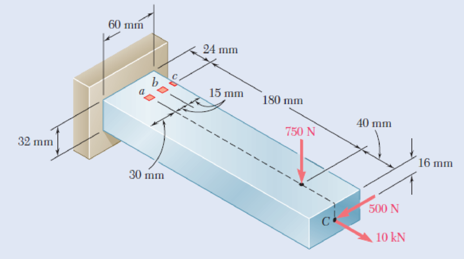
Three forces are applied to the bar shown. Determine the normal and shearing stresses at (a) point a, (b) point b, (c) point c.
Fig. P8.47
8.48 Solve Prob. 8.47, assuming that the 750-N force is directed vertically upward.
(a)
The normal and shearing stress at point a.
Answer to Problem 48P
The normal stress at point a is
The shear stress at point a is
Explanation of Solution
Given information:
Assume
Calculation:
At point A:
Find the area of cross section
Here, b is the width of the bar and h is the height of the bar.
Substitute
Find the moment of inertia
Substitute
Find the moment of inertia
Substitute
Sketch the side view of bar as shown in Figure 1.
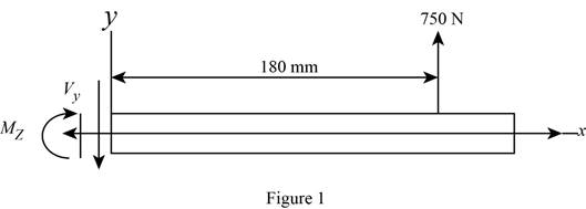
At the section containing point a, b, and c.
Refer to Figure 1.
Find the moment about z axis as follows:
Sketch the side view of bar as shown in Figure 2.
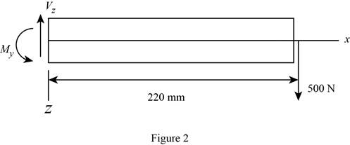
Find the moment about y axis as follows:
Find the normal stress
Here, P is the centric force, A is the area of rectangular cross section,
Substitute
Thus, the normal stress at point a is
Sketch the cross section at point a as shown in figure 3.
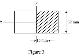
Determine the first moment area (Q) as follows:
Here,
Refer to Figure 2.
Substitute
Find the shear stress
Here,
Substitute
Thus, the shear stress at point a is
(b)
The normal and shearing stresses at point b.
Answer to Problem 48P
The normal stress at point b is
The shear stress at point b is
Explanation of Solution
Calculation:
At point b:
Find the normal stress
Substitute
Thus, the normal stress at point b is
Sketch the cross section at point b as shown in figure 4.
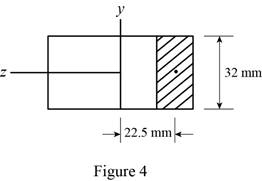
Determine the first moment area (Q) as follows:
Here,
Refer to Figure 2.
Substitute
Find the shear stress
Here,
Substitute
Thus, the shear stress at point b is
(c)
The normal and shearing stresses at point c.
Answer to Problem 48P
The normal stress at point c is
The shear stress at point c is
Explanation of Solution
Calculation:
Find the normal stress
Substitute
Thus, the normal stress at point c is
Find the shear stress
The point c is edge on the cross section. Since Q is zero.
Substitute
Thus, the shear stress at point c is
Want to see more full solutions like this?
Chapter 8 Solutions
Mechanics of Materials, 7th Edition
- Note: Please provide a clear, step-by-step simplified handwritten working out (no explanations!), ensuring it is done without any AI involvement. I require an expert-level answer, and I will assess and rate based on the quality and accuracy of your work and refer to the provided image for more clarity. Make sure to double-check everything for correctness before submitting appreciate your time and effort!. Question:arrow_forwardNote: Please provide a clear, step-by-step simplified handwritten working out (no explanations!), ensuring it is done without any AI involvement. I require an expert-level answer, and I will assess and rate based on the quality and accuracy of your work and refer to the provided image for more clarity. Make sure to double-check everything for correctness before submitting appreciate your time and effort!. Question: If the flow rate through the system below is 0.04m3s-1, find the difference in elevation H of the two reservoirs.arrow_forwardNote: Please provide a clear, step-by-step simplified handwritten working out (no explanations!), ensuring it is done without any AI involvement. I require an expert-level answer, and I will assess and rate based on the quality and accuracy of your work and refer to the provided image for more clarity. Make sure to double-check everything for correctness before submitting thanks!. Question: (In the image as provided)arrow_forward
- Note: Please provide a clear, step-by-step simplified handwritten working out (no explanations!), ensuring it is done without any AI involvement. I require an expert-level answer, and I will assess and rate based on the quality and accuracy of your work and refer to the provided image for more clarity. Make sure to double-check everything for correctness before submitting thanks!. Question: The rectangular gate shown below is 3 m wide. Compute the force P needed to hold the gate in the position shown.arrow_forwardNote: Please provide a clear, step-by-step simplified handwritten working out (no explanations!), ensuring it is done without any AI involvement. I require an expert-level answer, and I will assess and rate based on the quality and accuracy of your work and refer to the provided image for more clarity. Make sure to double-check everything for correctness before submitting thanks!. Question1: If the following container is 0.6m high, 1.2m wide and half full with water, determine the pressure acting at points A, B, and C if ax=2.6ms^-2.arrow_forwardPlease read the imagearrow_forward
- Chapter 12 - Lecture Notes.pptx: (MAE 272-01) (SP25) DY... Scoresarrow_forwardConsider a large 6-cm-thick stainless steel plate (k = 15.1 W/m-K) in which heat is generated uniformly at a rate of 5 × 10⁵ W/m³. Both sides of the plate are exposed to an environment at 30°C with a heat transfer coefficient of 60 W/m²K. Determine the value of the highest and lowest temperature. The highest temperature is The lowest temperature is °C. °C.arrow_forwardSketch and explain a PV Diagram and a Temperature Entropy Diagram for a 4 stroke diesel engine please, please explain into detail the difference bewteen the two and referance the a diagram. Please include a sketch or an image of each diagramarrow_forwardDraw left view of the first orthographic projectionarrow_forwardSketch and Describe a timing diagram for a 2 stroke diesel engine emphasis on the 2 stroke as my last answer explained 4 stroke please include a diagram or sketch.arrow_forwardA 4 ft 200 Ib 1000 Ib.ft C 2 ft 350 Ib - за в 2.5 ft 150 Ib 250 Ib 375 300 Ib Replace the force system acting on the frame. shown in the figure by a resultant force (magnitude and direction), and specify where its line of action intersects member (AB), measured from point (A).arrow_forwardarrow_back_iosSEE MORE QUESTIONSarrow_forward_ios
 Elements Of ElectromagneticsMechanical EngineeringISBN:9780190698614Author:Sadiku, Matthew N. O.Publisher:Oxford University Press
 Mechanics of Materials (10th Edition)Mechanical EngineeringISBN:9780134319650Author:Russell C. HibbelerPublisher:PEARSON
 Thermodynamics: An Engineering ApproachMechanical EngineeringISBN:9781259822674Author:Yunus A. Cengel Dr., Michael A. BolesPublisher:McGraw-Hill Education
 Control Systems EngineeringMechanical EngineeringISBN:9781118170519Author:Norman S. NisePublisher:WILEY
 Mechanics of Materials (MindTap Course List)Mechanical EngineeringISBN:9781337093347Author:Barry J. Goodno, James M. GerePublisher:Cengage Learning
 Engineering Mechanics: StaticsMechanical EngineeringISBN:9781118807330Author:James L. Meriam, L. G. Kraige, J. N. BoltonPublisher:WILEY


