
Concept explainers
Videos
8.9 through 8.14 Each of the following problems refers to a rolled-steel shape selected in a problem of Chap. 5 to support a given loading at a minimal cost while satisfying the requirement σm ≤ σall. For the selected design, determine (a) the actual value of σm in the beam, (b) the maximum value of the principal stress σmax at the junction of a flange and the web.
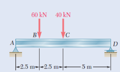
8.14 Loading of Prob. 5.78 and selected S460 × 81.4 shape.
Fig. P5.78
(a)
The actual value of
Answer to Problem 14P
The actual value of
Explanation of Solution
Given information:
Refer to problem 5.78 in chapter 5 in the textbook.
The allowable normal stress of the beam is
Calculation:
Design of beam:
Show the free-body diagram of the beam as in Figure 1.
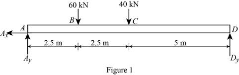
Determine the vertical reaction at point D by taking moment at point A.
Determine the vertical reaction at point A by resolving the vertical component of forces.
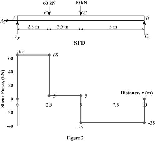
Shear force:
Show the calculation of shear force as follows;
Show the calculated shear force values as in Table 1.
| Location (x) m | Shear force (V) kN |
| A | 65 |
| B (Left) | 65 |
| B (Right) | 5 |
| C (Left) | 5 |
| C (Right) | –35 |
| D | –35 |
Plot the shear force diagram as in Figure 2.
Bending moment:
Show the calculation of the bending moment as follows;
Show the calculated bending moment values as in Table 2.
| Location (x) m | Bending moment (M) kN-m |
| A | 0 |
| B | 162.5 |
| C | 175 |
| D | 0 |
Plot the bending moment diagram as in Figure 3.
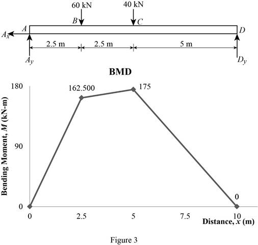
Refer to the Figure 3;
The maximum bending moment in the beam is
Write the section a property for a
| Dimension | Unit( |
| d | 457 |
| 152 | |
| 17.6 | |
Here, d is depth of the section,
Find the value of C using the relation:
Substitute
Find the maximum value of normal stress
Here,
Substitute
Thus, the actual value of
(b)
The maximum value of principal stress
Answer to Problem 14P
The maximum value of principal stress
Explanation of Solution
Calculation:
Find the value
Here, c is the centroid and
Substitute
Find the area of flange
Here,
Substitute
Find the centroid of flange
Substitute
Find the first moment about neutral axis
Here,
Substitute
At section C,
Find the value of
Here, actual value of normal stress
Substitute
Find the shear stress at
Modify Equation (8).
Substitute
Find the maximum shearing stress (R) using the relation:
Here,
Substitute
Determine the maximum value of the principle stress using the relation:
Here, R is the maximum shearing stress and
Substitute
At section B,
Find the maximum value of normal stress
Here,
Substitute
Find the value of
Substitute
Find the shear stress at b
Substitute
Refer to figure 3.
Substitute
Find the maximum shearing stress (R) using the relation:
Here,
Substitute
Determine the maximum value of the principle stress using the relation:
Here, R is the maximum shearing stress and
Substitute
Based on results,
Select the maximum value of principal stress
Thus, the maximum value of principal stress
Want to see more full solutions like this?
Chapter 8 Solutions
Mechanics of Materials, 7th Edition
Additional Engineering Textbook Solutions
Vector Mechanics For Engineers
Database Concepts (8th Edition)
Electric Circuits. (11th Edition)
Mechanics of Materials (10th Edition)
Thermodynamics: An Engineering Approach
Automotive Technology: Principles, Diagnosis, And Service (6th Edition) (halderman Automotive Series)


- 5: As shown, two aluminum rods AB and BC, hinged to rigid supports, arepinned together at B to carry a vertical load P = 6000 lb. If each rod has a crosssectional area of 0.60 in2 and E = 10 x 106 psi. Use α = θ = 30⁰. Calculate the change in length (in) of rod AB and indicate if it elongates orshortens. Calculate the vertical displacement of B (in) and horizontal displacement of B (in). Complete fbd.arrow_forward2: The rigid bar supports the uniform distributedload of 6 kip/ft. Determine the force in each cable if each cable has a cross-sectional area of 0.05 in^2 , and E = 31(10)^3 ksi.arrow_forwardIn (Figure 1), take m₁ = 4 kg and mB = 4.6 kg. Determine the z component of the angular momentum Ho of particle A about point O. Determine the z component of the angular momentum Ho of particle B about point O. Suppose that 5 m 8 m/s 4 m 1.5 m 4 m B MB 1 m 2 m 5 30° 6 m/s MAarrow_forward
- The two disks A and B have a mass of 4 kg and 6 kg, respectively. They collide with the initial velocities shown. The coefficient of restitution is e = 0.75. Suppose that (VA)1 = 6 m/s, (VB)₁ = 7 m/s. (Figure 1) Determine the magnitude of the velocity of A just after impact. Determine the angle between the x axis and the velocity of A just after impact, measured clockwise from the negative x axis. Determine the magnitude of the velocity of B just after impact. Determine the angle between the x axis and the velocity of B just after impact, measured clockwise from the positive x axis. (VB)1 B (VA)1 60° Line of impactarrow_forwardA hot plane surface is maintained at 100°C, and it is exposed to air at 25°C.The combined heat transfer coefficient between the surface and the air is 25W/m²·K. (same as above). In this task, you are asked to design fins to cool asurface by attaching 3 cm-long, 0.25 cm-diameter aluminum pin fins (thermalconductivity, k = 237 W/m·K) with a center-to-center distance of 0.6 cm. (Tip:do not correct the length). Determine the rate of heat transfer from thefinned structure to the air for a 1 m x 1 m section of the plate.arrow_forwardHeat is generated uniformly in a 4 cm-diameter, 16-cm long solid bar (k=2.4 W/m-K). The temperaturesat the center and at the surface of the bar are measured to be 210 oC and 45 oC, respectively. Calculatethe rate of heat generation within the bar. Solve the relevant energy balance equation and the boundaryconditions to calculate the rate of heat generation within the bar. (6 pts)arrow_forward
- A hot plane surface is maintained at 100°C, and it is exposed to air at 25°C. The combined heat transfercoefficient between the surface and the air is 25 W/m²·K. You are tasked with designing an insulatingmaterial to cover the surface in order to reduce the heat transfer rate by 90%, meaning only 10% of theheat transfer would occur compared to the situation without insulation. The available insulating materialhas a thermal conductivity of 0.093 W/m·K. Assuming that the heat transfer coefficient and the surface/airtemperatures remain constant, calculate the required thickness of the insulating material in centimeters.arrow_forwardThe euler parameter in the image describes the orientation of N in the reference frame of U. How do I find the euler parameters that describe the orientation of U in the reference frame of N from the given information in the image.arrow_forwardFpull Ө A person, weighing 155 lb, is being lifted by a rope thrown. over a tree branch as shown (drawing not to scale). If the static coefficient of friction between the rope and the tree branch is us = 0.67, and the 0 = 45°. Determine the pulling force required to start lifting the person and the pulling force required to keep the person from falling? Pulling force to lift the person: Pulling force to keep the person from falling: lb lbarrow_forward
- The car weighs 1630 lbs and drives up the hill at a constant speed. Assuming the static friction coefficient between the wheels and the road is μs = 0.64, determine the steepest angle that the car can climb without slipping if it is.... a.) rear wheel drive b.) front wheel drive c.) four wheel drive a C CC ①⑧ BY NC Dr. Jacob Moore Values for dimensions on the figure are given in the following table. Note the figure may not be to scale. Variable Value a 8.75 ft b 3.325 ft C 1.66 ft a.) The steepest angle for rear wheel drive is 0 max degrees. b.) The steepest angle for front wheel drive is Omax degrees. c.) The steepest angle for four wheel drive is Omax degrees. = = =arrow_forwardFor the structure below, each member of the truss will safely support a tensile force of 3 kN and a compressive force of 1 kN. Determine the largest mass m that can be safely suspended. Hint: First work through this algebraically to find the forces in each member terms of the mass "m" to determine the largest stress member. 1 m t 1 m 1 m 1m + 1m E B 1977 marrow_forwardBlock A has a mass of 34 kg and block B has a mass of 41 kg. The two blocks are stacked on the ramp with an incline of Ꮎ 0 = 15.4°. Determine the largest horizontal force F that can be applied to block B without either block moving for each of the following two cases: a.) The friction coefficient for the contact between blocks A and B is μs1 0.56 and the friction coefficient for the = contact between block A and the ramp is μs2 = 0.34. b.) The friction coefficient for the contact between blocks A and B is 1 = 0.56 and the friction coefficient for the contact between block A and the ramp is μs2 = 0.17. Ꮎ F B A Part a) The limiting slip condition occurs at Select an answer CC BY NC SA 2016 Eric Davishahl The maximum force before either block A or B slips is N Part b) The limiting slip condition occurs at Select an answer The maximum force before either block A or B slips is Narrow_forward
 Elements Of ElectromagneticsMechanical EngineeringISBN:9780190698614Author:Sadiku, Matthew N. O.Publisher:Oxford University Press
 Mechanics of Materials (10th Edition)Mechanical EngineeringISBN:9780134319650Author:Russell C. HibbelerPublisher:PEARSON
 Thermodynamics: An Engineering ApproachMechanical EngineeringISBN:9781259822674Author:Yunus A. Cengel Dr., Michael A. BolesPublisher:McGraw-Hill Education
 Control Systems EngineeringMechanical EngineeringISBN:9781118170519Author:Norman S. NisePublisher:WILEY
 Mechanics of Materials (MindTap Course List)Mechanical EngineeringISBN:9781337093347Author:Barry J. Goodno, James M. GerePublisher:Cengage Learning
 Engineering Mechanics: StaticsMechanical EngineeringISBN:9781118807330Author:James L. Meriam, L. G. Kraige, J. N. BoltonPublisher:WILEY