
Foundations of Materials Science and Engineering
6th Edition
ISBN: 9781259696558
Author: SMITH
Publisher: MCG
expand_more
expand_more
format_list_bulleted
Videos
Textbook Question
Chapter 8.15, Problem 41AAP
Consider the nickel–vanadium phase diagram of Figure P8.41.
- a. What is the maximum solid solubility of V in Ni while maintaining a single phase?
- b. At what temperature does the maximum solid solubility take place?
- c. Identify as many intermediate phases as you can.
- d. Identify at least one invariant reaction and provide as much information as possible for the reaction.
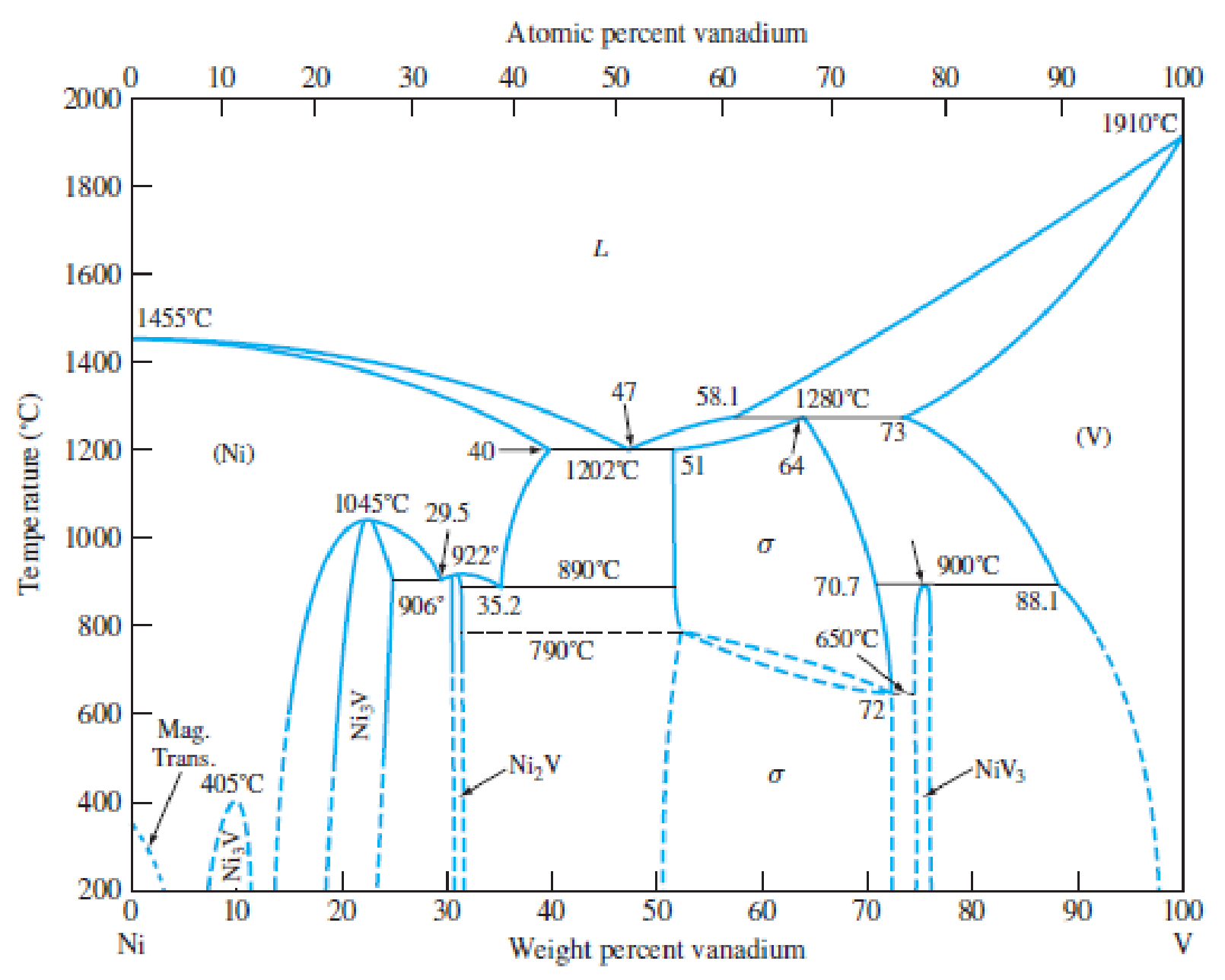
Figure P8.41
Nickel–vanadium phase diagram.
Expert Solution & Answer
Want to see the full answer?
Check out a sample textbook solution
Students have asked these similar questions
=
The forces F₁ = 590 lb, F₂ = 380 lb, F3 = 240 lb and F
330 lb. Determine the forces in each member of the truss.
Use positive values to indicate tension and negative values to
indicate compression.
a
a
a
D
b
F₁
A
000
B.
779977
F₂V
H
G
E
F4
b
BY NC SA
2013 Michael Swanbom
Values for dimensions on the figure are given in the following
table. Note the figure may not be to scale.
Variable Value
a
6 ft
b
10.1 ft
The force in member AB is
lb.
The force in member AH is
lb.
The force in member GH is
lb.
The force in member BH is
lb.
The force in member BC is
lb.
The force in member BG is
lb.
The force in member EG is
lb.
The force in member CD is
lb.
The force in member DE is
lb.
The force in member CE is
lb.
The force in member CG is
lb.
Multiple Choice
Circle the best answer to each statement.
1. Which type of surface deviation is controlled by a cy-
lindricity tolerance but not by a circularity tolerance?
A.
B.
C.
Ovality
Taper
Lobing
D. None of the above
2. When verifying a cylindricity tolerance, the inspec-
tion method must be able to collect a set of points and
determine the:
A. Distance between two coaxial cylinders that con-
tain the set of points
B.
Cylinder that circumscribes the set of points
C. Cylinder that inscribes the set of points
D.
Distance between two coaxial circles that contain
the set of points
3. Where Rule #1 applies to a cylindrical regular feature
of size, the tolerance value of a cylindricity tolerance
applied to the feature of size must be
tolerance.
A. Less than
B. Equal to
C. Greater than
D. None of the above
the size
4. Which of the following modifiers may be applied with
a cylindricity tolerance?
A. M
B.
C. ℗
D. Ø
5. Which geometric tolerance can provide an indirect
cylindricity…
The beam AB is attached to the wall in the xz plane by a
fixed support at A. A force of
F = (−129î + 69.0ĵ + 3591) N is applied to the end of
the beam at B. The weight of the beam can be modeled with
a uniform distributed load of intensity w = 85.0 N/m acting in
the negative z direction along its entire length. Find the
support reactions at A.
Z
с
A
b
a
B
F
y
Cc 10
BY NC SA
2016 Eric Davishahl
X
Values for dimensions on the figure are given in the following.
table. Note the figure may not be to scale.
Variable
Value
a
5.60 m
b
5.00 m
C
3.70 m
A
II
=
MA = (
m
2.>
~.>
+
+
k) N
k) N-
Chapter 8 Solutions
Foundations of Materials Science and Engineering
Ch. 8.15 - Define (a) a phase in a material and (b) a phase...Ch. 8.15 - In the pure water pressure-temperature equilibrium...Ch. 8.15 - How many triple points are there in the pure iron...Ch. 8.15 - Write the equation for the Gibbs phase rule and...Ch. 8.15 - Refer to the pressuretemperature equilibrium phase...Ch. 8.15 - (a) What is a cooling curve? (b) What type of...Ch. 8.15 - Prob. 7KCPCh. 8.15 - What is an alloy? What is the difference between...Ch. 8.15 - Prob. 9KCPCh. 8.15 - What is the significance of the liquidus curve?...
Ch. 8.15 - Prob. 11KCPCh. 8.15 - Prob. 12KCPCh. 8.15 - Prob. 13KCPCh. 8.15 - Describe the mechanism that produces the...Ch. 8.15 - Can coring and surrounding occur in a...Ch. 8.15 - What is a monotectic invariant reaction? How is...Ch. 8.15 - Write equations for the following invariant...Ch. 8.15 - How are eutectic and eutectoid reactions similar?...Ch. 8.15 - Distinguish between (a) a terminal phase and (b)...Ch. 8.15 - Distinguish between (a) an intermediate phase and...Ch. 8.15 - What is the difference between a congruently...Ch. 8.15 - Consider an alloy containing 70 wt% Ni and 30 wt%...Ch. 8.15 - Consider the binary eutectic coppersilver phase...Ch. 8.15 - If 500 g of a 40 wt% Ag60 wt% Cu alloy is slowly...Ch. 8.15 - A lead-tin (PbSn) alloy consists of 60 wt%...Ch. 8.15 - A PbSn alloy (Fig. 8.12) contains 40 wt% and 60...Ch. 8.15 - An alloy of 30 wt% Pb70 wt% Sn is slowly cooled...Ch. 8.15 - Consider the binary peritectic iridiumosmium phase...Ch. 8.15 - Consider the binary peritectic iridiumosmium phase...Ch. 8.15 - Consider the binary peritectic iridiumosmium phase...Ch. 8.15 - In the copperlead (CuPb) system (Fig. 8.24) for an...Ch. 8.15 - For an alloy of Cu70 wt% Pb (Fig. 8.24), determine...Ch. 8.15 - What is the average composition (weight percent)...Ch. 8.15 - Consider an Fe4.2 wt% Ni alloy (Fig. 8.17) that is...Ch. 8.15 - Consider an Fe5.0 wt% Ni alloy (Fig. 8.17) that is...Ch. 8.15 - Determine the weight percent and composition in...Ch. 8.15 - Determine the composition in weight percent of the...Ch. 8.15 - Draw, schematically, the liquidus and the solidus...Ch. 8.15 - Consider the CuZn phase diagram of Figure 8.26. a....Ch. 8.15 - Consider the nickelvanadium phase diagram of...Ch. 8.15 - Consider the titaniumaluminum phase diagram of...Ch. 8.15 - What is the composition of point y in Figure...Ch. 8.15 - In Figure 8.12, determine the degree of freedom,...Ch. 8.15 - The cooling curve of an unknown metal shows a...Ch. 8.15 - In the PbSn phase diagram (Fig. 8.12), answer the...Ch. 8.15 - Based on the CuAg phase diagram in Figure P8.23,...Ch. 8.15 - Based on the PdAg phase diagram in Figure EP 8.3,...Ch. 8.15 - Prob. 49SEPCh. 8.15 - Derive the lever rule for the amount in weight...Ch. 8.15 - Based on the AlNi phase diagram given in Figure...Ch. 8.15 - Prob. 52SEPCh. 8.15 - Based on the Al2O3SiO2 phase diagram in Figure...Ch. 8.15 - (a) Design a CuNi alloy that will be completely...Ch. 8.15 - Prob. 55SEPCh. 8.15 - Given that Pb and Sn have similar tensile...Ch. 8.15 - Consider the sugarwater phase diagram shown in...Ch. 8.15 - In Figure P8.57, if 60 g of water and 140 g of...Ch. 8.15 - In Figure P8.57, if 30 g of water and 170 g of...Ch. 8.15 - At 80C, if the wt% of sugar is 80%, (a) what...Ch. 8.15 - (a) Based on the phase diagram in Figure P8.61,...Ch. 8.15 - Referring to Figure P8.61. explain what happens as...Ch. 8.15 - Referring to Figure P8.61, (a) explain what...Ch. 8.15 - Using Figure P8.40, explain what the phase diagram...Ch. 8.15 - Using Figure P8.40. explain why, according to the...Ch. 8.15 - (a) In the TiAl phase diagram. Figure P8.42, what...Ch. 8.15 - Draw an approximate hypothetical phase diagram for...Ch. 8.15 - Draw the hypothetical phase diagram for a binary...
Knowledge Booster


Learn more about
Need a deep-dive on the concept behind this application? Look no further. Learn more about this topic, mechanical-engineering and related others by exploring similar questions and additional content below.Similar questions
- need help?arrow_forwardA bent pipe is attached to a wall with brackets as shown. A force of F = 180 lb is applied to the end of the tube with direction indicated by the dimensions in the figure. Determine the support reactions at the brackets B, C, and D. Model these brackets as journal bearings (only force reactions perpendicular to the axis of the tube) and neglect couple moment reactions. Assume the distance between the supports at B and C and the tube bends nearby are negligible such that the support at C is directly above the support at D and the dimension g gives the distance between supports B and C. Enter your answers in Cartesian components. 2013 Michael Swanbom cc 10 BY NC SA g h א B 8° У A C x каж Values for dimensions on the figure are given in the table below. Note the figure may not be to scale. Variable Value a 6.72 in b 11.8 in с 14.8 in d 42.0 in h 26.6 in g 28.0 in → The reaction at B is B = lb. The reaction at C is C = lb. The reaction at D is D = lb. + << + + 2. + + 557 〈んarrow_forwardThe force F1 = 10 kN, F2 = 10 kN, F3 = 10 kN, F4 = 5 KN are acting on the sttructure shown. Determine the forces in the members specified below. Use positive values to indicate tension and negative values to indicate compression. F2 D b F1 F3 C E b F4 b B F a G Values for dimensions on the figure are given in the following table. Note the figure may not be to scale. Variable Value a 3 m b 4 m The force in member BC is KN. The force in member BE is KN. The force in member EF is KN.arrow_forward
- h = The transmission tower is subjected to the forces F₁ 3.6 KN at 50° and F2 = 3.3 kN at = 35°. Determine the forces in members BC, BP, PQ, PC, CD, DP and NP. Use positive values to indicate tension and negative values to indicate compression. 不 кажаж в *а*аж E N M d d IF, c B CENTER LINE S อ K F₂ Kbb cc 10 BY NC SA 2013 Michael Swanbom Values for dimensions on the figure are given in the following table. Note the figure may not be to scale. Variable Value a 1.7 m b 4.9 m с 3 m d 5.2 m h 8.4 m Values for dimensions on the figure are given in the following table. Note the figure may not be to scale. Variable Value a 1.7 m 4.9 m с 3 m d 5.2 m h 8.4 m The force in member BC is KN. The force in member BP is KN. The force in member PQ is KN. The force in member PC is KN. The force in member CD is KN. The force in member DP is KN. The force in member NP is KN.arrow_forwardنصاف Sheet Asteel bar of rectangular cross section with dimension Shown in fig. below. This bar is as Connected toawell. Using welded Join a long the sides als only find the weld size (h). Where: Tall = 35 MN/M² F=213.30 answer/h= 4.04 ☐ Yomm Soomm 100mmarrow_forwardFEAarrow_forward
- FEAarrow_forwardHELP?arrow_forwardTrue and False Indicate if each statement is true or false. T/F 1. Rule #1 protects the function of assembly. T/F 2. One of the fundamental dimensioning rules requires all dimensions apply in the free-state condition for rigid parts. T/F 3. The fundamental dimensioning rules that apply on a drawing must be listed in the general notes. T/F 4. Where Rule #1 applies to a drawing, it limits the form of every feature of size on the drawing. T/F 5. Rule #1 limits the variation between features of size on a part. T/F 6. The designer must specify on the drawing which features of size use Rule #1. T/F T/F T/F 7. Rule #1 applies to nonrigid parts (in the unrestrained state). 8. A GO gage is a fixed-limit gage. 9. Rule #1 requires that the form of an individual regular feature of size is controlled by its limits of sizearrow_forward
arrow_back_ios
SEE MORE QUESTIONS
arrow_forward_ios
Recommended textbooks for you
 Elements Of ElectromagneticsMechanical EngineeringISBN:9780190698614Author:Sadiku, Matthew N. O.Publisher:Oxford University Press
 Mechanics of Materials (10th Edition)Mechanical EngineeringISBN:9780134319650Author:Russell C. HibbelerPublisher:PEARSON
 Thermodynamics: An Engineering ApproachMechanical EngineeringISBN:9781259822674Author:Yunus A. Cengel Dr., Michael A. BolesPublisher:McGraw-Hill Education
 Control Systems EngineeringMechanical EngineeringISBN:9781118170519Author:Norman S. NisePublisher:WILEY
 Mechanics of Materials (MindTap Course List)Mechanical EngineeringISBN:9781337093347Author:Barry J. Goodno, James M. GerePublisher:Cengage Learning
 Engineering Mechanics: StaticsMechanical EngineeringISBN:9781118807330Author:James L. Meriam, L. G. Kraige, J. N. BoltonPublisher:WILEY
Elements Of Electromagnetics
Mechanical Engineering
ISBN:9780190698614
Author:Sadiku, Matthew N. O.
Publisher:Oxford University Press
Mechanics of Materials (10th Edition)
Mechanical Engineering
ISBN:9780134319650
Author:Russell C. Hibbeler
Publisher:PEARSON
Thermodynamics: An Engineering Approach
Mechanical Engineering
ISBN:9781259822674
Author:Yunus A. Cengel Dr., Michael A. Boles
Publisher:McGraw-Hill Education
Control Systems Engineering
Mechanical Engineering
ISBN:9781118170519
Author:Norman S. Nise
Publisher:WILEY
Mechanics of Materials (MindTap Course List)
Mechanical Engineering
ISBN:9781337093347
Author:Barry J. Goodno, James M. Gere
Publisher:Cengage Learning
Engineering Mechanics: Statics
Mechanical Engineering
ISBN:9781118807330
Author:James L. Meriam, L. G. Kraige, J. N. Bolton
Publisher:WILEY
Material Science, Phase Diagrams, Part 1; Author: Welt der Werkstoffe;https://www.youtube.com/watch?v=G83ZaoB3XCc;License: Standard Youtube License