
Concept explainers
Videos
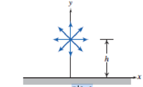
Carefully sketch the energy grade lines (EGL) and hydraulic grade lines (HGL) for the system shown in Fig. 6.6 if the pipe is horizontal (i.e., the outlet is at the base of the reservoir), and a water turbine (extracting energy) is located at point ②, or at point ③. In Chapter 8 we will investigate the effects of friction on internal flows. Can you anticipate and sketch the effect of friction on the EGL and HGL for the two cases?
P6.6
Want to see the full answer?
Check out a sample textbook solution
Chapter 6 Solutions
Fox and McDonald's Introduction to Fluid Mechanics
Additional Engineering Textbook Solutions
Starting Out with Programming Logic and Design (5th Edition) (What's New in Computer Science)
Computer Science: An Overview (13th Edition) (What's New in Computer Science)
Concepts Of Programming Languages
Thermodynamics: An Engineering Approach
Electric Circuits. (11th Edition)
Starting Out with Java: From Control Structures through Objects (7th Edition) (What's New in Computer Science)


- Create a schematic representation of the following mechanisms using the given symbols and draw their graphs. Then, calculate their degrees of freedom (DoF) using Gruebler's formula. PUNTO 6. PUNTO 7.arrow_forwardhow the kinematic diagram of the following mechanisms would be represented using the given symbols? PUNTO 0. PUNTO 1. °arrow_forwardCreate a schematic representation of the following mechanisms using the given symbols and draw their graphs. Then, calculate their degrees of freedom (DOF) using Gruebler's formula. PUNTO 4. PUNTO 5. (0) Groundarrow_forward
- Draw the graph of ALL the mechanisms and calculate their DoF using Gruebler's formula. PUNTO 0. PUNTO 1.arrow_forwardAn adjustable support. Construction designed to carry vertical load and is adjusted by moving the blue attachment vertically. The link is articulated at both ends (free to rotate) and can therefore only transmit power axially. Analytically calculate the force to which the link is subjected? Calculate analytically rated voltage in the middle of the link.? F=20kN Alpha 30 deg Rel 225 Mpans:5arrow_forwardA swivel crane where the load is moved axially along the beam through the wagon to which the hook is attached. Round bar with a diameter of ∅30 mm. The support beam is articulated at both ends (free to rotate) and can therefore only transmit force axially. Calculate reaction force in the x-direction at point A? Calculate analytical reaction force in the y-direction of point A? Calculate nominal stress in the middle of the support beam?Lengt 5 mAlfa 25 degX=1.5mIPE300-steelmass:1000 kgarrow_forward
- got wrong answers help pleasearrow_forwardA crate weighs 530 lb and is hung by three ropes attached to a steel ring at A such that the top surface is parallel to the xy plane. Point A is located at a height of h = 42 in above the top of the crate directly over the geometric center of the top surface. Use the dimensions given in the table below to determine the tension in each of the three ropes. 2013 Michael Swanbom cc00 BY NC SA ↑ Z C b B У a D Values for dimensions on the figure are given in the following table. Note the figure may not be to scale. Variable Value a 30 in b 43 in 4.5 in The tension in rope AB is 383 x lb The tension in rope AC is 156 x lb The tension in rope AD is 156 x lbarrow_forwardA block of mass m hangs from the end of bar AB that is 7.2 meters long and connected to the wall in the xz plane. The bar is supported at A by a ball joint such that it carries only a compressive force along its axis. The bar is supported at end B by cables BD and BC that connect to the xz plane at points C and D respectively with coordinates given in the figure. Cable BD is elastic and can be modeled as a linear spring with a spring constant k = 400 N/m and unstretched length of 6.34 meters. Determine the mass m, the compressive force in beam AB and the tension force in cable BC. Z C D (c, 0, d) (a, 0, b) A B y f m cc 10 BY NC SA 2016 Eric Davishahl x Values for dimensions on the figure are given in the following table. Note the figure may not be to scale. Variable Value a 8.1 m b 3.3 m с 2.7 m d 3.9 m e 2 m f 5.4 m The mass of the block is 68.8 The compressive force in bar AB is 364 × kg. × N. The tension in cable BC is 393 × N.arrow_forward
- The airplane weighs 144100 lbs and flies at constant speed and trajectory given by 0 on the figure. The plane experiences a drag force of 73620 lbs. 0 a.) If 11.3°, determine the thrust and lift forces = required to maintain this speed and trajectory. b.) Next consider the case where is unknown, but it is known that the lift force is equal to 7.8 times the quantity (Fthrust Fdrag). Compute the resulting trajectory angle and the lift force in this case. Use the same values for the weight and drag forces as you used for part a. 20. YAAY' Farag Ө Fthrust CC + BY NC SA 2013 Michael Swanbom Flift Fweight The lift force acts in the y' direction. The weight acts in the negative y direction. The thrust and drag forces act in the positive and negative x' directions respectively. Part (a) The thrust force is equal to 101,855 ☑ lbs. The lift force is equal to 141,282 ☑ lbs. Part (b) The trajectory angle 0 is equal to 7.31 ✓ deg. The lift force is equal to 143,005 ☑ lbs.arrow_forwardsimply supported beam has a concentrated moment M, applied at the left support and a concentrated force F applied at the free end of the overhang on the right. Using superposition, determine the deflection equations in regions AB and BC.arrow_forwardwhat is heat exchanger, what are formulas, and their importance, define the diagram, and give me a script on how to explain the design of heat exchanger, and how did values end up in that number. based on standards . what is dshellarrow_forward
 Elements Of ElectromagneticsMechanical EngineeringISBN:9780190698614Author:Sadiku, Matthew N. O.Publisher:Oxford University Press
 Mechanics of Materials (10th Edition)Mechanical EngineeringISBN:9780134319650Author:Russell C. HibbelerPublisher:PEARSON
 Thermodynamics: An Engineering ApproachMechanical EngineeringISBN:9781259822674Author:Yunus A. Cengel Dr., Michael A. BolesPublisher:McGraw-Hill Education
 Control Systems EngineeringMechanical EngineeringISBN:9781118170519Author:Norman S. NisePublisher:WILEY
 Mechanics of Materials (MindTap Course List)Mechanical EngineeringISBN:9781337093347Author:Barry J. Goodno, James M. GerePublisher:Cengage Learning
 Engineering Mechanics: StaticsMechanical EngineeringISBN:9781118807330Author:James L. Meriam, L. G. Kraige, J. N. BoltonPublisher:WILEY