Using the analyses of Example 6.1 and Problem 6.25, plot the discrepancy (percent) between the flow rates obtained from assuming uniform flow and the free vortex (irrotational) profile as a function of r 2 / r 1 . 25. Repeat Example 6.1, but with the somewhat more realistic assumption that the flow is similar to a free vortex (irrotational) profile, V θ = c / r (where c is a constant), as shown in Fig. P6.25. In doing so, prove that the flow rate is given by Q = k Δ p , where k is k = w ln ( r 2 r 1 ) 2 r 2 2 r 1 2 ρ ( r 2 2 − r 1 2 ) and w is the depth of the bend. P6.25
Using the analyses of Example 6.1 and Problem 6.25, plot the discrepancy (percent) between the flow rates obtained from assuming uniform flow and the free vortex (irrotational) profile as a function of r 2 / r 1 . 25. Repeat Example 6.1, but with the somewhat more realistic assumption that the flow is similar to a free vortex (irrotational) profile, V θ = c / r (where c is a constant), as shown in Fig. P6.25. In doing so, prove that the flow rate is given by Q = k Δ p , where k is k = w ln ( r 2 r 1 ) 2 r 2 2 r 1 2 ρ ( r 2 2 − r 1 2 ) and w is the depth of the bend. P6.25
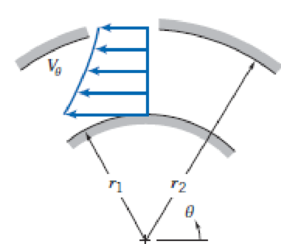
Using the analyses of Example 6.1 and Problem 6.25, plot the discrepancy (percent) between the flow rates obtained from assuming uniform flow and the free vortex (irrotational) profile as a function of r2/r1.
25. Repeat Example 6.1, but with the somewhat more realistic assumption that the flow is similar to a free vortex (irrotational) profile, Vθ = c/r (where c is a constant), as shown in Fig. P6.25. In doing so, prove that the flow rate is given by
Q
=
k
Δ
p
, where k is
k
=
w
ln
(
r
2
r
1
)
2
r
2
2
r
1
2
ρ
(
r
2
2
−
r
1
2
)
3 kN
3 kN
1.8 kN/m
80 mm
B
300 mm
D
an
1.5 m-1.5 m--1.5 m-
PROBLEM 5.47
Using the method of Sec. 5.2, solve Prob. 5.16
PROBLEM 5.16 For the beam and loading shown, determine the
maximum normal stress due to bending on a transverse section at C.
300 mm
3 kN
3 kN
450 N-m
D
E
200 mm
300 mm
PROBLEM 5.12
Draw the shear and bending-moment diagrams for the beam and loading
shown, and determine the maximum absolute value (a) of the shear,
(b) of the bending moment.
CORRECT AND DETAILED SOLUTION WITH FBD ONLY. I WILL UPVOTE THANK YOU. CORRECT ANSWER IS ALREADY PROVIDED. I REALLY NEED FBD.
The cantilevered spandrel beam shown whose depth tapers from d1 to d2, has a constant width of 120mm. It carries a triangularly distributed end reaction.Given: d1 = 600 mm, d2 = 120 mm, L = 1 m, w = 100 kN/m1. Calculate the maximum flexural stress at the support, in kN-m.2. Determine the distance (m), from the free end, of the section with maximum flexural stress.3. Determine the maximum flexural stress in the beam, in MPa.ANSWERS: (1) 4.630 MPa; (2) 905.8688 m; (3) 4.65 MPa
Chapter 6 Solutions
Fox and McDonald's Introduction to Fluid Mechanics
Thinking Like an Engineer: An Active Learning Approach (4th Edition)
Knowledge Booster
Learn more about
Need a deep-dive on the concept behind this application? Look no further. Learn more about this topic, mechanical-engineering and related others by exploring similar questions and additional content below.


 Elements Of ElectromagneticsMechanical EngineeringISBN:9780190698614Author:Sadiku, Matthew N. O.Publisher:Oxford University Press
 Mechanics of Materials (10th Edition)Mechanical EngineeringISBN:9780134319650Author:Russell C. HibbelerPublisher:PEARSON
 Thermodynamics: An Engineering ApproachMechanical EngineeringISBN:9781259822674Author:Yunus A. Cengel Dr., Michael A. BolesPublisher:McGraw-Hill Education
 Control Systems EngineeringMechanical EngineeringISBN:9781118170519Author:Norman S. NisePublisher:WILEY
 Mechanics of Materials (MindTap Course List)Mechanical EngineeringISBN:9781337093347Author:Barry J. Goodno, James M. GerePublisher:Cengage Learning
 Engineering Mechanics: StaticsMechanical EngineeringISBN:9781118807330Author:James L. Meriam, L. G. Kraige, J. N. BoltonPublisher:WILEY