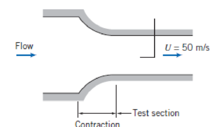
Problem 1P: An incompressible frictionless flow field is given by V=(Ax+By)i+(BxAy)j, where A = 2 s1 and B = 2... Problem 2P: A velocity field in a fluid with density of 1000 kg/m3 is given by V=(Ax+By)ti+(Ay+Bx)tj, where A =... Problem 3P: The x component of velocity in an incompressible flow field is given by u = Ax, where A = 2 s1 and... Problem 4P: Consider the flow field with the velocity given by V=3i+5tj+8t2k, where the velocity is in m/s and t... Problem 5P: Consider the flow field with the velocity given by V=4yi+3xj, where the velocity is in ft/s and the... Problem 6P: The velocity field for a plane source located distance h = 1m above an infinite wall aligned along... Problem 7P: In a two-dimensional frictionless, incompressible ( = 1500 kg/m3) flow, the velocity field in meters... Problem 8P: Consider a two-dimensional incompressible flow flowing downward against a plate. The velocity is... Problem 9P: An incompressible liquid with a density of 900 kg/m3 and negligible viscosity flows steadily through... Problem 10P: Consider a flow of water in pipe. What is the pressure gradient required to accelerate the water at... Problem 11P: The velocity field for a plane vortex sink is given by V=(q/2r)er+(K/2r)e, where q = 2 m3/s/m and K... Problem 12P: An incompressible liquid with negligible viscosity and density = 1.75 slug/ft3 flows steadily... Problem 13P: Consider water flowing in a circular section of a two-dimensional channel. Assume the velocity is... Problem 14P: Consider a tornado as air moving in a circular pattern in the horizontal plane. If the wind speed is... Problem 15P: A nozzle for an incompressible, inviscid fluid of density = 1000 kg/m3 consists of a horizontal... Problem 16P: A diffuser for an incompressible, inviscid fluid of density = 1000 kg/m3 consists of a horizontal... Problem 17P: A liquid layer separates two plane surfaces as shown. The lower surface is stationary; the upper... Problem 18P: Consider Problem 6.15 with the nozzle directed upward. Assuming that the flow is uniform at each... Problem 19P: Consider Problem 6.16 with the diffuser directed upward. Assuming that the flow is uniform at each... Problem 20P: A rectangular computer chip floats on a thin layer of air, h = 0.5 mm thick, above a porous surface.... Problem 21P: Heavy weights can be moved with relative ease on air cushions by using a load pallet as shown. Air... Problem 22P: The y component of velocity in a two-dimensional incompressible flow field is given by = Axy, where... Problem 23P: The velocity field for a plane doublet is given in Table 6.2. Find an expression for the pressure... Problem 24P: Tomodel the velocity distribution in the curved inlet section of a water channel, the radius of... Problem 25P: Repeat Example 6.1, but with the somewhat more realistic assumption that the flow is similar to a... Problem 26P: Using the analyses of Example 6.1 and Problem 6.25, plot the discrepancy (percent) between the flow... Problem 28P: Water flows at a speed of 25 ft/s. Calculate the dynamic pressure of this flow. Express your answer... Problem 29P: Plot the speed of air versus the dynamic pressure (in millimeters of mercury), up to a dynamic... Problem 30P: Water flows in a pipeline. At a point in the line where the diameter is 7 in., the velocity is 12... Problem 31P: In a pipe 0.3 m in diameter, 0.3 m3/s of water are pumped up a hill. On the hilltop (elevation 48),... Problem 32P: A jet of air from a nozzle is blown at right angles against a wall in which two pressure taps are... Problem 33P: The inlet contraction and test section of a laboratory wind tunnel are shown. The air speed in the... Problem 34P: Maintenance work on high-pressure hydraulic systems requires special precautions. A small leak can... Problem 35P: An open-circuit wind tunnel draws in air from the atmosphere through a well-contoured nozzle. In the... Problem 36P: Water is flowing. Calculate H(m) and p(kPa). P6.36 Problem 37P: If each gauge shows the same reading for a flow rate of 1.00 cfs, what is the diameter of the... Problem 38P: Derive a relation between A1 and A2 so that for a flow rate of 0.28 m3/s the static pressure will be... Problem 39P: Water flows steadily up the vertical 1 -in.-diameter pipe and out the nozzle, which is 0.5 in. in... Problem 40P: Your car runs out of gas unexpectedly and you siphon gas from another car. The height difference for... Problem 41P: A tank at a pressure of 50 kPa gage gets a pinhole rupture and benzene shoots into the air. Ignoring... Problem 42P: The water flow rate through the siphon is 5 L/s, its temperature is 20C, and the pipe diameter is 25... Problem 43P: Water flows from a very large tank through a 5 cm diameter tube. The dark liquid in the manometer is... Problem 44P: Consider frictionless, incompressible flow of air over the wing of an airplane flying at 200 km/hr.... Problem 45P: A closed tank contains water with air above it. The air is maintained at a gage pressure of 150 kPa... Problem 46P: Water jets upward through a 3-in.-diameter nozzle under a head of 10 ft. At what height h will the... Problem 47P: Calculate the rate of flow through this pipeline and the pressures at A, B, C, and D. Sketch the EL... Problem 48P: A mercury barometer is carried in a car on a day when there is no wind. The temperature is 20C and... Problem 49P: A racing car travels at 235 mph along a straightaway. The team engineer wishes to locate an air... Problem 50P: The velocity field for a plane source at a distance h above an infinite wall aligned along the x... Problem 51P: A smoothly contoured nozzle, with outlet diameter d = 20 mm, is coupled to a straight pipe by means... Problem 52P: Water flows steadily through a 3.25-in.-diameter pipe and discharges through a 1.25-in.-diameter... Problem 53P: A flow nozzle is a device for measuring the flow rate in a pipe. This particular nozzle is to be... Problem 54P: The head of water on a 50 mm diameter smooth nozzle is 3 m. If the nozzle is directed upward at... Problem 55P: Water flows from one reservoir in a 200-mm pipe, while water flows from a second reservoir in a... Problem 56P: Barometric pressure is 14.0 psia. What is the maximum flow rate that can be obtained by opening the... Problem 57P: A spray system is shown in the diagram. Water is supplied at p = 10 kPa gage, through the flanged... Problem 58P: Water flows out of a kitchen faucet of 1.25-in.-diameter at the rate of 0.1 L/s. The bottom of the... Problem 59P: A horizontal axisymmetric jet of air with 0.4-in.-diameter strikes a stationary vertical disk of 7.5... Problem 60P: The water level in a large tank is maintained at height H above the surrounding level terrain. A... Problem 61P: Many recreation facilities use inflatable bubble structures. A tennis bubble to enclose four courts... Problem 62P: Water flows at low speed through a circular tube with inside diameter of 2 in. A smoothly contoured... Problem 63P: Describe the pressure distribution on the exterior of a multistory building in a steady wind.... Problem 64P: An aspirator provides suction by using a stream of water flowing through a venturi. Analyze the... Problem 65P: Carefully sketch the energy grade lines (EGL) and hydraulic grade lines (HGL) for the system shown... Problem 66P: Carefully sketch the energy grade lines (EGL) and hydraulic grade lines (HGL) for the system shown... Problem 67P: Water is being pumped from the lower reservoir through a nozzle into the upper reservoir. If the... Problem 68P: The turbine extracts power from the water flowing from the reservoir. Find the horsepower extracted... Problem 69P: Consider a two-dimensional fluid flow: u = ax + by and = cx + dy, where a, b, c, and d are... Problem 70P: The velocity field for a two-dimensional flow is V=(AxBy)ti(Bx+Ay)tj, where A = 1 s2 B = 2 s2, t is... Problem 71P: A flow field is characterized by the stream function = Axy, where A = 2 s1 and the coordinates are... Problem 72P: The flow field for a plane source at a distance h above an infinite wall aligned along the x axis is... Problem 73P: The stream function of a flow field is = Ax2y By3, where A = 1 m1 s1, B=13m1s1, and the... Problem 74P: A flow field is characterized by the stream function =2y+12(tan1yaxtan1y+ax) Derive an expression... Problem 75P: A flow field is characterized by the stream function =xy2+Bx3 What does the value of B need to be... Problem 76P: The stream function of a flow field is = Ax3 Bxy2, where A = 1 m1 s1 and B = 3 m1 s1, and... Problem 77P: A flow field is represented by the stream function = x5 15x4y2 + 15x2y4 y6. Find the... Problem 78P: Consider the flow field represented by the potential function = x5 10x3y2 + 5xy4 x2 + y2. Verify... Problem 79P: Show by expanding and collecting real and imaginary terms that f = z6 (where z is the complex number... Problem 80P: Consider the flow field represented by the velocity potential = Ax + Bx2 By2, where A = 1 ms1, B =... Problem 81P: An incompressible flow field is characterized by the stream function = 3Ax2y Ay3, where A = 1 m1 ... Problem 82P: Consider an air flow over a flat wall with an upstream velocity of 6 m/s. There is a narrow slit... Problem 83P: A source with a strength of q = 3 m2/s and a sink with a strength of q = m2/s are located on the x... Problem 84P: The velocity distribution in a two-dimensional, steady, inviscid flow field in the xy plane is... Problem 85P: Consider the flow past a circular cylinder, of radius a, used in Example 6.11. Show that Vr = 0... Problem 86P: The flow in a corner with an angle can be described in radial coordinates by the stream function as... Problem 87P: Consider the two-dimensional flow against a flat plate that is characterized by the stream function ... Problem 88P: A source and a sink with strengths of equal magnitude, q = 3 m2/s, are placed on the x axis at x = a... Problem 89P: A flow field is formed by combining a uniform flow in the positive x direction, with U = 10 m/s, and... format_list_bulleted


 Elements Of ElectromagneticsMechanical EngineeringISBN:9780190698614Author:Sadiku, Matthew N. O.Publisher:Oxford University Press
 Mechanics of Materials (10th Edition)Mechanical EngineeringISBN:9780134319650Author:Russell C. HibbelerPublisher:PEARSON
 Thermodynamics: An Engineering ApproachMechanical EngineeringISBN:9781259822674Author:Yunus A. Cengel Dr., Michael A. BolesPublisher:McGraw-Hill Education
 Control Systems EngineeringMechanical EngineeringISBN:9781118170519Author:Norman S. NisePublisher:WILEY
 Mechanics of Materials (MindTap Course List)Mechanical EngineeringISBN:9781337093347Author:Barry J. Goodno, James M. GerePublisher:Cengage Learning
 Engineering Mechanics: StaticsMechanical EngineeringISBN:9781118807330Author:James L. Meriam, L. G. Kraige, J. N. BoltonPublisher:WILEY