
Control Systems Engineering
7th Edition
ISBN: 9781118170519
Author: Norman S. Nise
Publisher: WILEY
expand_more
expand_more
format_list_bulleted
Videos
Textbook Question
Chapter 4, Problem 55P
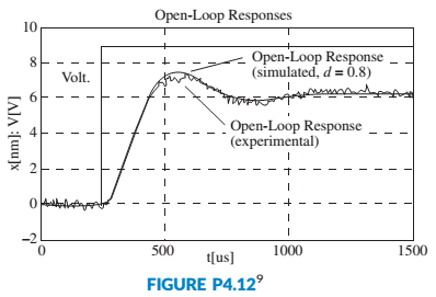
A MOEMS (optical MEMS) is a MEMS (Micro Electromechanical Systems) with an optical fiber channel that takes light generated from a laser diode. It also has a photodetector that measures light intensity variations and outputs voltage variations proportional to small  in any dimension. Figure P4.12 shows input-output signal pairs used to identify the parameters of the system. Assume a second-order transfer function and find the system’s transfer function (Borovic, 2005).
Expert Solution & Answer
Want to see the full answer?
Check out a sample textbook solution
Students have asked these similar questions
using the theorem of three moments, find all the moments, I need concise calculations only
Practise question need help on
Can you show explaination and working. The answer from the text book is Q=5.03 X 10^-3
Chapter 4 Solutions
Control Systems Engineering
Ch. 4 - Prob. 1RQCh. 4 - What does the performance specification for a...Ch. 4 - Prob. 3RQCh. 4 - In a system with an input and an output, what...Ch. 4 - Prob. 5RQCh. 4 - Prob. 6RQCh. 4 - 7. What is the difference between the natural...Ch. 4 - Prob. 8RQCh. 4 - Prob. 9RQCh. 4 - Prob. 10RQ
Ch. 4 - List five specifications for a second-order...Ch. 4 - Prob. 12RQCh. 4 - What pole locations characterize (1) the...Ch. 4 - Prob. 14RQCh. 4 - How can you justify pole-zero cancellation?Ch. 4 - Prob. 16RQCh. 4 - 17. What is the relationship between , which...Ch. 4 - Name a major advantage of using time-domain...Ch. 4 - Prob. 19RQCh. 4 - What three pieces of information must be given in...Ch. 4 - 21. How can the poles of a system be found from...Ch. 4 - Prob. 1PCh. 4 - Prob. 2PCh. 4 - MATIAB ML 3. Plot the step responses for Problem 2...Ch. 4 - Find the capacitor voltage in the network shown in...Ch. 4 - For the system shown in Figure P4.3, (a) find an...Ch. 4 - Prob. 8PCh. 4 - MATLAB ML 9. Use MATLAB to find the poles of...Ch. 4 - Find the transfer function and poles of the system...Ch. 4 - MATLAB ML 11. Repeat Problem 10 using MATLAB....Ch. 4 - Write the general form of the capacitor voltage...Ch. 4 - Solve for x(t) in the system shown in Figure P4.5...Ch. 4 - Prob. 15PCh. 4 - Prob. 16PCh. 4 - Calculate the exact response of each system of...Ch. 4 - Prob. 18PCh. 4 - Prob. 19PCh. 4 - For each of the second-order systems that follow,...Ch. 4 - MATLAB ML 21. Repeat Problem 20 using MATLAB. Have...Ch. 4 - GUI Tool GUIT
22. Use MATLAB’s LTI Viewer and...Ch. 4 - Prob. 23PCh. 4 - Find the transfer function of a second-order...Ch. 4 - For the system shown in Figure P4.7, do the...Ch. 4 - For the system shown in Figure P4.8, a step torque...Ch. 4 - Prob. 28PCh. 4 - Prob. 29PCh. 4 - Prob. 30PCh. 4 - Prob. 31PCh. 4 - Prob. 32PCh. 4 - Prob. 33PCh. 4 - Prob. 34PCh. 4 - Prob. 35PCh. 4 - Prob. 36PCh. 4 - State Space SS 38. A system is represented by the...Ch. 4 - Prob. 39PCh. 4 - Prob. 40PCh. 4 - State Space SS 41. Given the following system...Ch. 4 - State Space SS 42. Solve the following state...Ch. 4 - Prob. 43PCh. 4 - Prob. 44PCh. 4 - Prob. 46PCh. 4 - Prob. 47PCh. 4 - Prob. 48PCh. 4 - Prob. 53PCh. 4 - Prob. 54PCh. 4 - A MOEMS (optical MEMS) is a MEMS (Micro...Ch. 4 - Prob. 56PCh. 4 - Prob. 59PCh. 4 - Prob. 60PCh. 4 - Prob. 61PCh. 4 - Prob. 63PCh. 4 - Prob. 67PCh. 4 - Figure P4.l6 shows the step response of an...Ch. 4 - Figure P4. I 7 shows the free-body diagrams for...Ch. 4 - Find an equation that relates 2% settling time to...Ch. 4 - Prob. 74PCh. 4 - Prob. 75PCh. 4 - 76. Find J and K in the rotational system shown in...Ch. 4 - Given the system shown in Figure P4.22, find the...Ch. 4 - Prob. 78PCh. 4 - Find M and K, shown in the system of Figure P4.24,...Ch. 4 - If vi(t) is a step voltage in the network shown in...Ch. 4 - Prob. 81PCh. 4 - Prob. 82PCh. 4 - For the circuit shown in Figure P4.26, find the...Ch. 4 - Prob. 84PCh. 4 - Prob. 86P
Knowledge Booster


Learn more about
Need a deep-dive on the concept behind this application? Look no further. Learn more about this topic, mechanical-engineering and related others by exploring similar questions and additional content below.Similar questions
- practise questionarrow_forwardCan you provide steps and an explaination on how the height value to calculate the Pressure at point B is (-5-3.5) and the solution is 86.4kPa.arrow_forwardPROBLEM 3.46 The solid cylindrical rod BC of length L = 600 mm is attached to the rigid lever AB of length a = 380 mm and to the support at C. When a 500 N force P is applied at A, design specifications require that the displacement of A not exceed 25 mm when a 500 N force P is applied at A For the material indicated determine the required diameter of the rod. Aluminium: Tall = 65 MPa, G = 27 GPa. Aarrow_forward
- Find the equivalent mass of the rocker arm assembly with respect to the x coordinate. k₁ mi m2 k₁arrow_forward2. Figure below shows a U-tube manometer open at both ends and containing a column of liquid mercury of length l and specific weight y. Considering a small displacement x of the manometer meniscus from its equilibrium position (or datum), determine the equivalent spring constant associated with the restoring force. Datum Area, Aarrow_forward1. The consequences of a head-on collision of two automobiles can be studied by considering the impact of the automobile on a barrier, as shown in figure below. Construct a mathematical model (i.e., draw the diagram) by considering the masses of the automobile body, engine, transmission, and suspension and the elasticity of the bumpers, radiator, sheet metal body, driveline, and engine mounts.arrow_forward
- 3.) 15.40 – Collar B moves up at constant velocity vB = 1.5 m/s. Rod AB has length = 1.2 m. The incline is at angle = 25°. Compute an expression for the angular velocity of rod AB, ė and the velocity of end A of the rod (✓✓) as a function of v₂,1,0,0. Then compute numerical answers for ȧ & y_ with 0 = 50°.arrow_forward2.) 15.12 The assembly shown consists of the straight rod ABC which passes through and is welded to the grectangular plate DEFH. The assembly rotates about the axis AC with a constant angular velocity of 9 rad/s. Knowing that the motion when viewed from C is counterclockwise, determine the velocity and acceleration of corner F.arrow_forward500 Q3: The attachment shown in Fig.3 is made of 1040 HR. The static force is 30 kN. Specify the weldment (give the pattern, electrode number, type of weld, length of weld, and leg size). Fig. 3 All dimension in mm 30 kN 100 (10 Marks)arrow_forward
- (read image) (answer given)arrow_forwardA cylinder and a disk are used as pulleys, as shown in the figure. Using the data given in the figure, if a body of mass m = 3 kg is released from rest after falling a height h 1.5 m, find: a) The velocity of the body. b) The angular velocity of the disk. c) The number of revolutions the cylinder has made. T₁ F Rd = 0.2 m md = 2 kg T T₂1 Rc = 0.4 m mc = 5 kg ☐ m = 3 kgarrow_forward(read image) (answer given)arrow_forward
arrow_back_ios
SEE MORE QUESTIONS
arrow_forward_ios
Recommended textbooks for you
 Understanding Motor ControlsMechanical EngineeringISBN:9781337798686Author:Stephen L. HermanPublisher:Delmar Cengage Learning
 Electrical Transformers and Rotating MachinesMechanical EngineeringISBN:9781305494817Author:Stephen L. HermanPublisher:Cengage Learning
Understanding Motor Controls
Mechanical Engineering
ISBN:9781337798686
Author:Stephen L. Herman
Publisher:Delmar Cengage Learning
Electrical Transformers and Rotating Machines
Mechanical Engineering
ISBN:9781305494817
Author:Stephen L. Herman
Publisher:Cengage Learning
Thermodynamic Availability, What is?; Author: MechanicaLEi;https://www.youtube.com/watch?v=-04oxjgS99w;License: Standard Youtube License