
Electrical Engineering: Principles & Applications, 7th Edition
7th Edition
ISBN: 9780134485201
Author: Allan R. Hambley
Publisher: PEARSON
expand_more
expand_more
format_list_bulleted
Videos
Textbook Question
Chapter 4, Problem 4.23P
In the circuit of Figure P4.23, the switch is in position A for a long time prior to
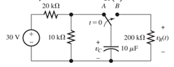
Figure P4.23
Expert Solution & Answer
Want to see the full answer?
Check out a sample textbook solution
Students have asked these similar questions
. Using Properties to find the Z-Transform including the region of convergence for
x(n) = n
(2)" cos(0.2π(n − 2))u(n − 1)
-
-
J
VDD
M₁
In the circuit of figure shown below, determine the region of operation of M₁as Vigoes from VDD.to
zero. (You may want to draw a plot or just explain by the range, remember the transistor is a PMOS)
Assume VDD = 2.5 V and | VTH | = 0.4V.
5
+
1 V
We wish to design the circuit of the figure shown below for a drain current of 1 mA (l=1mA).
If W/L = 18/0.18, compute R1 and R2 such that the input impedance is at least 20 k.
R₁
VDD = 1.8 V
500 Ω
M₁
R₂
Chapter 4 Solutions
Electrical Engineering: Principles & Applications, 7th Edition
Ch. 4 - Suppose we have a capacitance C discharging...Ch. 4 - The dielectric materials used in real capacitors...Ch. 4 - The initial voltage across the capacitor shown in...Ch. 4 - A 100F capacitance is initially charged to 1000 V....Ch. 4 - At t = 0, a charged 10{ F capacitance is connected...Ch. 4 - At time t1 , a capacitance C is charged to a...Ch. 4 - Given an initially charged capacitance that begins...Ch. 4 - The initial voltage across the capacitor shown in...Ch. 4 - In physics, the half-life is often used to...Ch. 4 - We know that a 50F capacitance is charged to an...
Ch. 4 - We know that the capacitor shown in Figure P4.11...Ch. 4 - The purchasing power P of a certain unit of...Ch. 4 - Derive an expression for vC(t) in the circuit of...Ch. 4 - Suppose that at t= 0, we connect an uncharged 10 F...Ch. 4 - Suppose we have a capacitance C that is charged to...Ch. 4 - A person shuffling across a dry carpet can be...Ch. 4 - Prob. 4.17PCh. 4 - Consider the circuit shown in Figure P4.18. Prior...Ch. 4 - List the steps for dc steady-state analysis of RLC...Ch. 4 - Explain why we replace capacitances with open...Ch. 4 - Solve for the steady-state values of i1, i2, and...Ch. 4 - Consider the circuit shown in Figure P4.22. What...Ch. 4 - In the circuit of Figure P4.23, the switch is in...Ch. 4 - The circuit shown in Figure P4.24 has been set up...Ch. 4 - Solve for the steady-state values of i1 , i2, i3,...Ch. 4 - The circuit shown in Figure P4.26 is operating in...Ch. 4 - Prob. 4.27PCh. 4 - Consider the circuit of Figure P4.28 in which the...Ch. 4 - For the circuit shown in Figure P4.29, the switch...Ch. 4 - Consider the circuit of Figure P4.30 in which the...Ch. 4 - Give the expression for the time constant of a...Ch. 4 - A circuit consists of switches that open or close...Ch. 4 - The circuit shown in Figure P4.33 is operating in...Ch. 4 - Consider the circuit shown in Figure P4.34. The...Ch. 4 - Repeat Problem P4.34 given iL(0)=0A .Ch. 4 - Real inductors have series resistance associated...Ch. 4 - Determine expressions for and sketch is(t) to...Ch. 4 - For the circuit shown in Figure P4.38,, find an...Ch. 4 - The circuit shown in Figure P4.39 is operating in...Ch. 4 - Consider the circuit shown in Figure P4.40. A...Ch. 4 - Due to components not shown in the figure, the...Ch. 4 - The switch shown in Figure P4.42 has been closed...Ch. 4 - Determine expressions for and sketch vR(t) to...Ch. 4 - What are the steps in solving a circuit having a...Ch. 4 - Prob. 4.45PCh. 4 - Solve for vC(t) for t > 0 in the circuit of Figure...Ch. 4 - Solve for v(t) for t > 0 in the circuit of Figure...Ch. 4 - Prob. 4.48PCh. 4 - Consider the circuit shown inFigure P4.49. The...Ch. 4 - Consider the circuit shown in Figure P4.50. The...Ch. 4 - The voltage source shown in Figure P4.51 is called...Ch. 4 - Determine the form of the particular solution for...Ch. 4 - Determine the form of the particular solution for...Ch. 4 - Prob. 4.54PCh. 4 - Prob. 4.55PCh. 4 - How can first-or second-order circuits be...Ch. 4 - Prob. 4.57PCh. 4 - Prob. 4.58PCh. 4 - Prob. 4.59PCh. 4 - Sketch a step response for a second-order system...Ch. 4 - A dc source is connected to a series RLC circuit...Ch. 4 - Repeat Problem P4.61 for R = 40 .Ch. 4 - Repeat Problem P4.61 for R = 20 .Ch. 4 - Prob. 4.64PCh. 4 - Repeat Problem P4.64 for R=50 .Ch. 4 - Repeat Problem P4.64 for R=500 .Ch. 4 - Solve for i(t) for t > 0 in the circuit of Figure...Ch. 4 - Prob. 4.68PCh. 4 - Prob. 4.69PCh. 4 - Prob. 4.70PCh. 4 - Use MATLAB to derive an expression for vc(t)in the...Ch. 4 - Prob. 4.72PCh. 4 - Consider the circuit shown in FigureP4.50 in which...Ch. 4 - Prob. 4.74PCh. 4 - Prob. 4.75PCh. 4 - Use MATLAB to solve for the mesh currents in the...Ch. 4 - The switch m the circuit shown in Figure T4.1 is...Ch. 4 - Prob. 4.2PTCh. 4 - Consider the circuit shown in Figure T4.3. Figure...Ch. 4 - Consider the circuit shown in Figure T4.4 in which...Ch. 4 - Write the MATLAB commands to obtain the solution...
Knowledge Booster


Learn more about
Need a deep-dive on the concept behind this application? Look no further. Learn more about this topic, electrical-engineering and related others by exploring similar questions and additional content below.Similar questions
- In the figure shown below, what is the minimum allowable value of VDD if M₁ must not enter the triode region? Assume λ=0 (use ideal current formula that is not dependent on VDs) 1 V + RD VDD = 1.8 V T M 500 Ω 1 W 10 L = 0.18arrow_forwardCalculate the total charge stored in the channel of an NMOS device if Cox=10fF/um², w=10 µm, L=0.1 μm, and VGS-VTH=1 V. Assume VDs=0. (means there is no movement of electrons, all of them are piled up in the channel, we want to calculate the magnitude of electron charge |Q|)arrow_forwardThe first photo is question 1arrow_forward
- a) Write down the order of the transfer function in each of the following cases. Assume that there are no terms in the numerator that will cancel terms in the denominator. 10 H(s) H(s) = s+1 5 (s+3)(s—. 4) 4s1 5 H(s) = H(s) - 83 +1 s27s 6 H(s) H(s) = s(s²+4s) 2s27s+1 84583882 +3s+2 H(s) 83 +8 s+1 = H(s) s34s26s+5 s52s4383 + 4s2 +5s +6arrow_forwardQuestion 5 ( A system is found to have zeros of -3 and poles of 4, and -2. The system also has a gain of 4. Write out the corresponding transfer function. Question 6. A system has a transfer function of What is the gain, K, of the system? Question 7 ( A system has a transfer function of H(s) - 4 8+5 H(s): = 4 8 +5 A step input of size 3 is applied to the system at time zero (Since we're dealing with transfer functions, x(0) is also zero at time zero). a) [10] What is the response ✗(s) of the system? b) [10] Derive the time dependent solution, x(t), of this responsearrow_forwardNote: You might want to do the last question first because the last question asks you to write some python code to calculate the zeros and poles. You could use that code here to help you (except the first problem which you should be able to do by inspection alone) Find the poles and zeros for each of the following transfer functions 1. S+3 H(s) = 8 5 2. H(s): = s238 +1 s2 +48 +3 3. s(s+4) H(s) s3+2s23s 4. 82-586 H(s) = - 8382-68 5. H(s): = s2 +48 +3 s45836s2 - 6arrow_forward
- Write python program to plot the zeros and poles if a user provides the coefficients for the numerator and denominator of the transfer function. Since the zeros and poles can be complex, this plot is essentially and argand diagram, where the x axis is the real component and the y axis the imaginary component of a given zero or pole. Create a method called plot-poles zeros(num, den) which takes two lists containing the coefficients. Here is an example and the resulting plot. num [1, 3, 7] # yields zeros at -1.5 +/- 2.17945j den = [1, 4, 5, 3] # yields poles at -2.46557, -0.7672143 +/- 0.7925519j plot_poles_zeros(num, den) Imaginary Page 2 Pole-Zero Plot 3 Zeros × Poles 2 1 -2 1 * Real When you write your code you are only allowed to use the packages numpy and matplotlib. Make sure you label the axes, provide a legend and give a title to your plot (See the example plot). Hint: numpy has a method called roots. When given a list of numbers corresponding to the coefficients of a polynomial,…arrow_forwarda) [10] Compute the zeros and poles for the following transfer function: $2 +5s+6 H(s): s2 +3s+2 b) [10] Factor both polynomials in the numerator and denominator. What does this tell you about one of the poles and zeros you found in a)?arrow_forwardPls show neat and whole solutionarrow_forward
arrow_back_ios
SEE MORE QUESTIONS
arrow_forward_ios
Recommended textbooks for you
 Introductory Circuit Analysis (13th Edition)Electrical EngineeringISBN:9780133923605Author:Robert L. BoylestadPublisher:PEARSON
 Delmar's Standard Textbook Of ElectricityElectrical EngineeringISBN:9781337900348Author:Stephen L. HermanPublisher:Cengage Learning
 Programmable Logic ControllersElectrical EngineeringISBN:9780073373843Author:Frank D. PetruzellaPublisher:McGraw-Hill Education
 Fundamentals of Electric CircuitsElectrical EngineeringISBN:9780078028229Author:Charles K Alexander, Matthew SadikuPublisher:McGraw-Hill Education
 Electric Circuits. (11th Edition)Electrical EngineeringISBN:9780134746968Author:James W. Nilsson, Susan RiedelPublisher:PEARSON
 Engineering ElectromagneticsElectrical EngineeringISBN:9780078028151Author:Hayt, William H. (william Hart), Jr, BUCK, John A.Publisher:Mcgraw-hill Education,
Introductory Circuit Analysis (13th Edition)
Electrical Engineering
ISBN:9780133923605
Author:Robert L. Boylestad
Publisher:PEARSON
Delmar's Standard Textbook Of Electricity
Electrical Engineering
ISBN:9781337900348
Author:Stephen L. Herman
Publisher:Cengage Learning
Programmable Logic Controllers
Electrical Engineering
ISBN:9780073373843
Author:Frank D. Petruzella
Publisher:McGraw-Hill Education
Fundamentals of Electric Circuits
Electrical Engineering
ISBN:9780078028229
Author:Charles K Alexander, Matthew Sadiku
Publisher:McGraw-Hill Education
Electric Circuits. (11th Edition)
Electrical Engineering
ISBN:9780134746968
Author:James W. Nilsson, Susan Riedel
Publisher:PEARSON
Engineering Electromagnetics
Electrical Engineering
ISBN:9780078028151
Author:Hayt, William H. (william Hart), Jr, BUCK, John A.
Publisher:Mcgraw-hill Education,
ECE320 Lecture1-3c: Steady-State Error, System Type; Author: Rose-Hulman Online;https://www.youtube.com/watch?v=hG7dq-51AAg;License: Standard Youtube License