
Videos
Consider the circuit of Figure P4.30 in which the switch has been closed for a long time prior to t = 0. Determine the values of
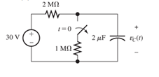
Figure P4.30
Want to see the full answer?
Check out a sample textbook solution
Chapter 4 Solutions
Electrical Engineering: Principles & Applications, 7th Edition


- a. An average hole drift velocity of 103 cm/sec results when 2V is applied across a 1 cm long semiconductor bar. What is the hole mobility inside the bar? b. Name the two dominant carrier scattering mechanisms in nondegeneratedly doped semiconductors of device quality. c. For a give semiconductor the carrier mobilities in intrinsic material are (choose one: higher than, lower than, the same as) those in heavily doped material. Briefly explain why the mobilites in intrinsic material are (chosen answer) those in heavily doped material.arrow_forwardFind the steady-state expression for vo(t) in the following circuit if vg (t) = 64 cos(8000t) V. 31.25 nF HE + Vg + - 2 ΚΩ Vo 500 mHarrow_forwardUse PSpice to model the differential amplifier circuit shown in Fig. 4 in DIBO mode (double input balanced output). Use 2N3904 BJTs and use appropriate values for resistors (you can choose the values that will not lead to excessive gain and saturation) to demonstrate that the circuit provides differential amplification. Use Vcc = 5 and Vee = 5. Use a pair of sinusoids with opposing polarity (180 degree phase shift) as the inputs to the differential amplifier. Recall from the theory ic is needed to compute re. Make sure that the conditions set in the analysis of DIBO circuit are satisfied. Assume Rs1 = Rs2 50 Ω. Does your simulation match the theoretical gain? Explain any differences.arrow_forward
- Derive the expression for the voltage gain of DIBO differential amplifier using AC analysis.arrow_forwardConsider the following circuit. + - 1.2 ΚΩ ig (1) vo ΣΕ ΚΩ € 50 nF 200 mH a) [6 pts] The frequency of the source current in the circuit is adjusted until vo is in phase with ig. What is the value of o in radians per second? (Hint: if vo is in phase with ig, the phase of total impedance must be zero (Ztot = vol ig), which means the phase of total admittance is zero. It will be easy to work with admittance in this question because the components are in parallel.) b) [2 pts] What is the total impedance at the frequency found in (a)? c) [2 pts] Ifig=2.5 cosoot mA (where o is the frequency found in [a]), what is the steady-state expression for vo?arrow_forwardConsider the following circuit with ig (t) = 200 cos(5000t) mA. 240 ΩΣ + 80 2: 2.5 µF 48 mH a) [3 pts] Obtain and draw the frequency-domain circuit. b) [3 pts] Use the current division to find the current flowing through the 240 2 resistor. c) [3 pts] Then calculate Vo in phasor form. d) [1 pts] Write the steady-state expression for vo(t).arrow_forward
- Q-Draw a sample and hold electronic circuit using op-amp then explain its operation. I hope the solution is from a human being and not from intelligencearrow_forwardDesign an AC-coupled (input and output) amplifier with a gain of -8 which has identical 3 dB corner frequencies of 10 kHz for high pass coupling at the input and output. Assume a power supply of 5 volts.arrow_forwardFind Laplace inverse for -25 -1 e S-1arrow_forward
- This question and its solution. Is the solution correct? If the solution is correct, assume that let R2 = 20 and a=500 . If it is wrong, solve it in your own way, away from the sources, and explain to me in detail with a pen and paper, please.arrow_forwardcan you compute the values inside the blue circles using the data from the plan above them? Please disregard the values (data/numbers) inside the circles.arrow_forwardThe average output voltage is found from Vac = = 2 2π/6 3√3 π -V #16 m √√3V™ cos ot d (ot) 0 = 1.654Vm m where Vm, is the peak phase voltage. I want detailed integration steps and how you reached this result.arrow_forward
 Introductory Circuit Analysis (13th Edition)Electrical EngineeringISBN:9780133923605Author:Robert L. BoylestadPublisher:PEARSON
 Delmar's Standard Textbook Of ElectricityElectrical EngineeringISBN:9781337900348Author:Stephen L. HermanPublisher:Cengage Learning
 Programmable Logic ControllersElectrical EngineeringISBN:9780073373843Author:Frank D. PetruzellaPublisher:McGraw-Hill Education
 Fundamentals of Electric CircuitsElectrical EngineeringISBN:9780078028229Author:Charles K Alexander, Matthew SadikuPublisher:McGraw-Hill Education
 Electric Circuits. (11th Edition)Electrical EngineeringISBN:9780134746968Author:James W. Nilsson, Susan RiedelPublisher:PEARSON
 Engineering ElectromagneticsElectrical EngineeringISBN:9780078028151Author:Hayt, William H. (william Hart), Jr, BUCK, John A.Publisher:Mcgraw-hill Education,