
Electrical Engineering: Principles & Applications, 7th Edition
7th Edition
ISBN: 9780134485201
Author: Allan R. Hambley
Publisher: PEARSON
expand_more
expand_more
format_list_bulleted
Videos
Textbook Question
Chapter 4, Problem 4.21P
Solve for the steady-state values of
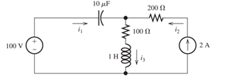
Figure P4.21
Expert Solution & Answer
Want to see the full answer?
Check out a sample textbook solution
Students have asked these similar questions
4. Consider the following fluid system consisting of two tanks.
Bult)
Assume, R = 10, p = 1, g = 10 and ẞ = 1.
a) Find the differential equation of the system.
b) Find the transfer function (s)
U(s)
Q13
3. Consider the following thermal system with two objects. Assume both objects have
the same thermal capacity C and the thermal resistance of the separating conductor
is R. Suppose the heat flow to the left object is u(t) Joule/s.
a) Find the differential equation model of the system.
T₂(s)
b) Find the transfer function
U(s)*
T1
Τε
N
Chapter 4 Solutions
Electrical Engineering: Principles & Applications, 7th Edition
Ch. 4 - Suppose we have a capacitance C discharging...Ch. 4 - The dielectric materials used in real capacitors...Ch. 4 - The initial voltage across the capacitor shown in...Ch. 4 - A 100F capacitance is initially charged to 1000 V....Ch. 4 - At t = 0, a charged 10{ F capacitance is connected...Ch. 4 - At time t1 , a capacitance C is charged to a...Ch. 4 - Given an initially charged capacitance that begins...Ch. 4 - The initial voltage across the capacitor shown in...Ch. 4 - In physics, the half-life is often used to...Ch. 4 - We know that a 50F capacitance is charged to an...
Ch. 4 - We know that the capacitor shown in Figure P4.11...Ch. 4 - The purchasing power P of a certain unit of...Ch. 4 - Derive an expression for vC(t) in the circuit of...Ch. 4 - Suppose that at t= 0, we connect an uncharged 10 F...Ch. 4 - Suppose we have a capacitance C that is charged to...Ch. 4 - A person shuffling across a dry carpet can be...Ch. 4 - Prob. 4.17PCh. 4 - Consider the circuit shown in Figure P4.18. Prior...Ch. 4 - List the steps for dc steady-state analysis of RLC...Ch. 4 - Explain why we replace capacitances with open...Ch. 4 - Solve for the steady-state values of i1, i2, and...Ch. 4 - Consider the circuit shown in Figure P4.22. What...Ch. 4 - In the circuit of Figure P4.23, the switch is in...Ch. 4 - The circuit shown in Figure P4.24 has been set up...Ch. 4 - Solve for the steady-state values of i1 , i2, i3,...Ch. 4 - The circuit shown in Figure P4.26 is operating in...Ch. 4 - Prob. 4.27PCh. 4 - Consider the circuit of Figure P4.28 in which the...Ch. 4 - For the circuit shown in Figure P4.29, the switch...Ch. 4 - Consider the circuit of Figure P4.30 in which the...Ch. 4 - Give the expression for the time constant of a...Ch. 4 - A circuit consists of switches that open or close...Ch. 4 - The circuit shown in Figure P4.33 is operating in...Ch. 4 - Consider the circuit shown in Figure P4.34. The...Ch. 4 - Repeat Problem P4.34 given iL(0)=0A .Ch. 4 - Real inductors have series resistance associated...Ch. 4 - Determine expressions for and sketch is(t) to...Ch. 4 - For the circuit shown in Figure P4.38,, find an...Ch. 4 - The circuit shown in Figure P4.39 is operating in...Ch. 4 - Consider the circuit shown in Figure P4.40. A...Ch. 4 - Due to components not shown in the figure, the...Ch. 4 - The switch shown in Figure P4.42 has been closed...Ch. 4 - Determine expressions for and sketch vR(t) to...Ch. 4 - What are the steps in solving a circuit having a...Ch. 4 - Prob. 4.45PCh. 4 - Solve for vC(t) for t > 0 in the circuit of Figure...Ch. 4 - Solve for v(t) for t > 0 in the circuit of Figure...Ch. 4 - Prob. 4.48PCh. 4 - Consider the circuit shown inFigure P4.49. The...Ch. 4 - Consider the circuit shown in Figure P4.50. The...Ch. 4 - The voltage source shown in Figure P4.51 is called...Ch. 4 - Determine the form of the particular solution for...Ch. 4 - Determine the form of the particular solution for...Ch. 4 - Prob. 4.54PCh. 4 - Prob. 4.55PCh. 4 - How can first-or second-order circuits be...Ch. 4 - Prob. 4.57PCh. 4 - Prob. 4.58PCh. 4 - Prob. 4.59PCh. 4 - Sketch a step response for a second-order system...Ch. 4 - A dc source is connected to a series RLC circuit...Ch. 4 - Repeat Problem P4.61 for R = 40 .Ch. 4 - Repeat Problem P4.61 for R = 20 .Ch. 4 - Prob. 4.64PCh. 4 - Repeat Problem P4.64 for R=50 .Ch. 4 - Repeat Problem P4.64 for R=500 .Ch. 4 - Solve for i(t) for t > 0 in the circuit of Figure...Ch. 4 - Prob. 4.68PCh. 4 - Prob. 4.69PCh. 4 - Prob. 4.70PCh. 4 - Use MATLAB to derive an expression for vc(t)in the...Ch. 4 - Prob. 4.72PCh. 4 - Consider the circuit shown in FigureP4.50 in which...Ch. 4 - Prob. 4.74PCh. 4 - Prob. 4.75PCh. 4 - Use MATLAB to solve for the mesh currents in the...Ch. 4 - The switch m the circuit shown in Figure T4.1 is...Ch. 4 - Prob. 4.2PTCh. 4 - Consider the circuit shown in Figure T4.3. Figure...Ch. 4 - Consider the circuit shown in Figure T4.4 in which...Ch. 4 - Write the MATLAB commands to obtain the solution...
Knowledge Booster


Learn more about
Need a deep-dive on the concept behind this application? Look no further. Learn more about this topic, electrical-engineering and related others by exploring similar questions and additional content below.Similar questions
- 2. Consider the DC motor differential equation derived in the class. Suppose we are driving the motor with constant input ū. a) Find the expression for steady-state angular speed of the motor in terms of ū and motor parameters J, L, R, K, Ka and b. di dw = Note that in steady state, 0. dt dt b) Looking at the expression you have for speed of the motor, suggest a parameter that you should change to increase the speed.arrow_forwardA classroom has 10 students, and 4 of them are to be selected to give presentations. In how many ways can the teacher assign a different order for the presentation?arrow_forwardHW_#5 uah.instructure.com zm Rich LTI Z (MAE 272-01) (SP25) DYN... Answered: Page of 2... Gadjoint of a 2x2 matrix - G... R Inverse Matrix Calculator G what is a singular matrix -... HW_05.pdf EE 213-01 Assignments 1) Use mesh analysis to determine values for the mesh currents I1, 12 and 13. Use these mesh currents to find node voltages V1, V2 and current I I1 10 V + √2 15K V1 5K + 10K VD 3 mA ІЗ 20K 12 1 mA VREF 2) The resistor R is adjusted until the power dissipated in the resistor is maximized. Find the value of R that results in maximum power transferred to the resistor R and that maximum power. Hint: find the Thevenin equivalent circuit for the circuit to the left of terminals a-b. To find the Thevenin circuit, find the open circuit voltage and the short circuit current at terminals a-b. a + 100 V 100 Ohms 50 Ohms 10 Ohms R 4 Amps 10 Ohms b ✓ Download → Info × Close - ZOOM + File Previewarrow_forward
- A student has 8 different books and wats to arrange 5 of them in a row on a shelf. How many different arrangements are possible?arrow_forwardA state issues license plates that consist of 3 letters followed by 4 digits (e.g., ABC1234). If repetition of letters and digits is allowed, how many unique license plates can be created?arrow_forwardQ9arrow_forward
- Measure the impedance (magnitude and phase) of the inductor including the internal resistance at a frequency of1kHz. (Determine the reactance and internal resistance of the inductor.) How would use of an osciloscope help solve this problem?arrow_forwardnot use ai pleasearrow_forwardSketch the phasor diagram of the peak voltage across the capacitor VC and peak current IC in the circuit shownbelow. How would use of an osciloscope aid in solving this problem?arrow_forward
- Sketch the phasor diagram of the rms voltage across the inductor vL and rms source VS in the circuit shown below. how would use of an osciloscope help solve this problem?arrow_forwardThe attached waveform VS displayed on the oscilloscope approximate the following quantities.1. The peak voltage.2. The peak-to-peak voltage.3. The frequency of the waveform.4. The difference in time that corresponds to a 72 degree phase shift for this waveform. How would use of an osciloscope aid in solving this problem?arrow_forwardVs -J XcR Wo R²=3JRX < -Xc * Xc = ± Wc How do I make this Vs equation Look? ✓ = 3 + 1 (RWC- RWC) Vo 3+arrow_forward
arrow_back_ios
SEE MORE QUESTIONS
arrow_forward_ios
Recommended textbooks for you
 Introductory Circuit Analysis (13th Edition)Electrical EngineeringISBN:9780133923605Author:Robert L. BoylestadPublisher:PEARSON
 Delmar's Standard Textbook Of ElectricityElectrical EngineeringISBN:9781337900348Author:Stephen L. HermanPublisher:Cengage Learning
 Programmable Logic ControllersElectrical EngineeringISBN:9780073373843Author:Frank D. PetruzellaPublisher:McGraw-Hill Education
 Fundamentals of Electric CircuitsElectrical EngineeringISBN:9780078028229Author:Charles K Alexander, Matthew SadikuPublisher:McGraw-Hill Education
 Electric Circuits. (11th Edition)Electrical EngineeringISBN:9780134746968Author:James W. Nilsson, Susan RiedelPublisher:PEARSON
 Engineering ElectromagneticsElectrical EngineeringISBN:9780078028151Author:Hayt, William H. (william Hart), Jr, BUCK, John A.Publisher:Mcgraw-hill Education,
Introductory Circuit Analysis (13th Edition)
Electrical Engineering
ISBN:9780133923605
Author:Robert L. Boylestad
Publisher:PEARSON
Delmar's Standard Textbook Of Electricity
Electrical Engineering
ISBN:9781337900348
Author:Stephen L. Herman
Publisher:Cengage Learning
Programmable Logic Controllers
Electrical Engineering
ISBN:9780073373843
Author:Frank D. Petruzella
Publisher:McGraw-Hill Education
Fundamentals of Electric Circuits
Electrical Engineering
ISBN:9780078028229
Author:Charles K Alexander, Matthew Sadiku
Publisher:McGraw-Hill Education
Electric Circuits. (11th Edition)
Electrical Engineering
ISBN:9780134746968
Author:James W. Nilsson, Susan Riedel
Publisher:PEARSON
Engineering Electromagnetics
Electrical Engineering
ISBN:9780078028151
Author:Hayt, William H. (william Hart), Jr, BUCK, John A.
Publisher:Mcgraw-hill Education,
ECE320 Lecture1-3c: Steady-State Error, System Type; Author: Rose-Hulman Online;https://www.youtube.com/watch?v=hG7dq-51AAg;License: Standard Youtube License