
Electrical Engineering: Principles & Applications, 7th Edition
7th Edition
ISBN: 9780134485201
Author: Allan R. Hambley
Publisher: PEARSON
expand_more
expand_more
format_list_bulleted
Concept explainers
Videos
Textbook Question
Chapter 4, Problem 4.33P
The circuit shown in Figure P4.33 is operating in steady state with the switch closed prior to t = 0. Find i(t) for t < 0 and for
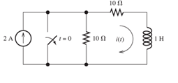
Figure P4.33
Expert Solution & Answer

Learn your wayIncludes step-by-step video

schedule05:45
Students have asked these similar questions
Vs
-J XcR
Wo
R²=3JRX < -Xc
* Xc = ±
Wc
How do I make this
Vs
equation Look?
✓ = 3 + 1 (RWC- RWC)
Vo
3+
Draw the complete circular stator winding for a three
phase delta connected AC generator consisting of 4 poles
and 24 slots using a parallel connection. Your submission
must consist of two drawings as follows:
One drawing must show the winding arrangement of the
phasegroups in the slots of the stator highlighting the
start and finish of each phasegroup
The other drawing must show only the end connections of
each phase group for a parallel connection of the
phasegroups and a delta connection of the phases
The use of AutoCad or any other software is encouraged.
For the oscillator resonance circuit shown in Fig. (5), derive the oscillation frequency,
Feedback and open-loop gains.
R1
C1
C2
ww
R2
HH
Fig.(5)
Chapter 4 Solutions
Electrical Engineering: Principles & Applications, 7th Edition
Ch. 4 - Suppose we have a capacitance C discharging...Ch. 4 - The dielectric materials used in real capacitors...Ch. 4 - The initial voltage across the capacitor shown in...Ch. 4 - A 100F capacitance is initially charged to 1000 V....Ch. 4 - At t = 0, a charged 10{ F capacitance is connected...Ch. 4 - At time t1 , a capacitance C is charged to a...Ch. 4 - Given an initially charged capacitance that begins...Ch. 4 - The initial voltage across the capacitor shown in...Ch. 4 - In physics, the half-life is often used to...Ch. 4 - We know that a 50F capacitance is charged to an...
Ch. 4 - We know that the capacitor shown in Figure P4.11...Ch. 4 - The purchasing power P of a certain unit of...Ch. 4 - Derive an expression for vC(t) in the circuit of...Ch. 4 - Suppose that at t= 0, we connect an uncharged 10 F...Ch. 4 - Suppose we have a capacitance C that is charged to...Ch. 4 - A person shuffling across a dry carpet can be...Ch. 4 - Prob. 4.17PCh. 4 - Consider the circuit shown in Figure P4.18. Prior...Ch. 4 - List the steps for dc steady-state analysis of RLC...Ch. 4 - Explain why we replace capacitances with open...Ch. 4 - Solve for the steady-state values of i1, i2, and...Ch. 4 - Consider the circuit shown in Figure P4.22. What...Ch. 4 - In the circuit of Figure P4.23, the switch is in...Ch. 4 - The circuit shown in Figure P4.24 has been set up...Ch. 4 - Solve for the steady-state values of i1 , i2, i3,...Ch. 4 - The circuit shown in Figure P4.26 is operating in...Ch. 4 - Prob. 4.27PCh. 4 - Consider the circuit of Figure P4.28 in which the...Ch. 4 - For the circuit shown in Figure P4.29, the switch...Ch. 4 - Consider the circuit of Figure P4.30 in which the...Ch. 4 - Give the expression for the time constant of a...Ch. 4 - A circuit consists of switches that open or close...Ch. 4 - The circuit shown in Figure P4.33 is operating in...Ch. 4 - Consider the circuit shown in Figure P4.34. The...Ch. 4 - Repeat Problem P4.34 given iL(0)=0A .Ch. 4 - Real inductors have series resistance associated...Ch. 4 - Determine expressions for and sketch is(t) to...Ch. 4 - For the circuit shown in Figure P4.38,, find an...Ch. 4 - The circuit shown in Figure P4.39 is operating in...Ch. 4 - Consider the circuit shown in Figure P4.40. A...Ch. 4 - Due to components not shown in the figure, the...Ch. 4 - The switch shown in Figure P4.42 has been closed...Ch. 4 - Determine expressions for and sketch vR(t) to...Ch. 4 - What are the steps in solving a circuit having a...Ch. 4 - Prob. 4.45PCh. 4 - Solve for vC(t) for t > 0 in the circuit of Figure...Ch. 4 - Solve for v(t) for t > 0 in the circuit of Figure...Ch. 4 - Prob. 4.48PCh. 4 - Consider the circuit shown inFigure P4.49. The...Ch. 4 - Consider the circuit shown in Figure P4.50. The...Ch. 4 - The voltage source shown in Figure P4.51 is called...Ch. 4 - Determine the form of the particular solution for...Ch. 4 - Determine the form of the particular solution for...Ch. 4 - Prob. 4.54PCh. 4 - Prob. 4.55PCh. 4 - How can first-or second-order circuits be...Ch. 4 - Prob. 4.57PCh. 4 - Prob. 4.58PCh. 4 - Prob. 4.59PCh. 4 - Sketch a step response for a second-order system...Ch. 4 - A dc source is connected to a series RLC circuit...Ch. 4 - Repeat Problem P4.61 for R = 40 .Ch. 4 - Repeat Problem P4.61 for R = 20 .Ch. 4 - Prob. 4.64PCh. 4 - Repeat Problem P4.64 for R=50 .Ch. 4 - Repeat Problem P4.64 for R=500 .Ch. 4 - Solve for i(t) for t > 0 in the circuit of Figure...Ch. 4 - Prob. 4.68PCh. 4 - Prob. 4.69PCh. 4 - Prob. 4.70PCh. 4 - Use MATLAB to derive an expression for vc(t)in the...Ch. 4 - Prob. 4.72PCh. 4 - Consider the circuit shown in FigureP4.50 in which...Ch. 4 - Prob. 4.74PCh. 4 - Prob. 4.75PCh. 4 - Use MATLAB to solve for the mesh currents in the...Ch. 4 - The switch m the circuit shown in Figure T4.1 is...Ch. 4 - Prob. 4.2PTCh. 4 - Consider the circuit shown in Figure T4.3. Figure...Ch. 4 - Consider the circuit shown in Figure T4.4 in which...Ch. 4 - Write the MATLAB commands to obtain the solution...
Additional Engineering Textbook Solutions
Find more solutions based on key concepts
The following is a multiplication problem in traditional base ten notation. Each letter represents a different ...
Computer Science: An Overview (13th Edition) (What's New in Computer Science)
If the block is held in the equilibrium position shown, determine the mass of the block at D.
INTERNATIONAL EDITION---Engineering Mechanics: Statics, 14th edition (SI unit)
Determine the maximum normal stress developed in the bar when it is subjected to a tension of P = 8kN.
Mechanics of Materials (10th Edition)
3.1 Discuss the differences between an error and a residual.
Elementary Surveying: An Introduction To Geomatics (15th Edition)
In the following exercises, write a program to carry out the task. The program should use variables for each of...
Introduction To Programming Using Visual Basic (11th Edition)
Distinguish among data definition commands, data manipulation commands, and data control commands.
Modern Database Management
Knowledge Booster


Learn more about
Need a deep-dive on the concept behind this application? Look no further. Learn more about this topic, electrical-engineering and related others by exploring similar questions and additional content below.Similar questions
- 1. (30pts) The input to a system is a DC component, a message, m(t), and a carrier, c(t). The output of the system is the square of the sum of the inputs. Determine if it is possible to retrieve DSB-SC modulated waveform. Show your work.arrow_forward2) (20pts) m(t) and an unmodulated carrier, c(t), are given below m(t) = 2.2 cos(2л400t) – 7 cos(2л700t) +5 cos(2500) volts c(t) = 6 cos(2л2000) volts Sketch the amplitude spectrum for a Double Sideband Suppressed Carrier modulated waveform. You must carefully label all axes and provide each frequency component value (the x-value); each amplitude in Volts/Hz (the y-value). Include both negative and positive frequencies.arrow_forwardnot use ai pleasearrow_forward
- For the circuit shown, find the voltage vo using superposition. Let Vs1-11, V2=27 V, 1-4, R₁-8 02, R2=5 Q2, R3-17 02, R4-2002 and R5-14 02. In particular show your values for: V01, Vo due to Is only: V01- V02, Vo due to V51 only: Voz V03, Vo due to V52 only: V03= Then Vo Vo VSI +1 RI ww ww V. IS V. V. V. R3 R5 ww www + Vo R2 www R4 V$2 The relative tolerance for this problem is 10 %.arrow_forwardFor the circuit shown, let V-28, I-5, R₁=50, R₂-802, R3-2002, R4-17 2 and R5-11 Q, determine the maximum power dissipated by the load resistor R₁ as follows: ■ Find VTH seen by the load resistor R₁, VTh= (V) (50%) ⚫ {Hint: You can use superposition or any other method. } Find RTH seen by the load resistor RL, RT= (Q) (25%) ■ maximum power dissipated by the load resistor R₁: (W) (25%) Is R5 R 1 ww w R3 Vs ± R2 w R4 w RL + Vo The relative tolerance for this problem is 10 %.arrow_forward3) (40 pts) An FM modulated carrier is modulated by the following signal: m(t) = 4 cos(2л * (1000) *t) volts The modulator uses a frequency deviation of 3 KHz. The unmodulated carrier is: * c(t) = 5 cos(2π (100,000) *t) volts a) (10pts) What would be a good estimate of the bandwidth of modulated signal?arrow_forward
arrow_back_ios
SEE MORE QUESTIONS
arrow_forward_ios
Recommended textbooks for you
 Introductory Circuit Analysis (13th Edition)Electrical EngineeringISBN:9780133923605Author:Robert L. BoylestadPublisher:PEARSON
 Delmar's Standard Textbook Of ElectricityElectrical EngineeringISBN:9781337900348Author:Stephen L. HermanPublisher:Cengage Learning
 Programmable Logic ControllersElectrical EngineeringISBN:9780073373843Author:Frank D. PetruzellaPublisher:McGraw-Hill Education
 Fundamentals of Electric CircuitsElectrical EngineeringISBN:9780078028229Author:Charles K Alexander, Matthew SadikuPublisher:McGraw-Hill Education
 Electric Circuits. (11th Edition)Electrical EngineeringISBN:9780134746968Author:James W. Nilsson, Susan RiedelPublisher:PEARSON
 Engineering ElectromagneticsElectrical EngineeringISBN:9780078028151Author:Hayt, William H. (william Hart), Jr, BUCK, John A.Publisher:Mcgraw-hill Education,
Introductory Circuit Analysis (13th Edition)
Electrical Engineering
ISBN:9780133923605
Author:Robert L. Boylestad
Publisher:PEARSON
Delmar's Standard Textbook Of Electricity
Electrical Engineering
ISBN:9781337900348
Author:Stephen L. Herman
Publisher:Cengage Learning
Programmable Logic Controllers
Electrical Engineering
ISBN:9780073373843
Author:Frank D. Petruzella
Publisher:McGraw-Hill Education
Fundamentals of Electric Circuits
Electrical Engineering
ISBN:9780078028229
Author:Charles K Alexander, Matthew Sadiku
Publisher:McGraw-Hill Education
Electric Circuits. (11th Edition)
Electrical Engineering
ISBN:9780134746968
Author:James W. Nilsson, Susan Riedel
Publisher:PEARSON
Engineering Electromagnetics
Electrical Engineering
ISBN:9780078028151
Author:Hayt, William H. (william Hart), Jr, BUCK, John A.
Publisher:Mcgraw-hill Education,
Capacitors Explained - The basics how capacitors work working principle; Author: The Engineering Mindset;https://www.youtube.com/watch?v=X4EUwTwZ110;License: Standard YouTube License, CC-BY