
Electrical Engineering: Principles & Applications, 7th Edition
7th Edition
ISBN: 9780134485201
Author: Allan R. Hambley
Publisher: PEARSON
expand_more
expand_more
format_list_bulleted
Concept explainers
Videos
Textbook Question
Chapter 4, Problem 4.11P
We know that the capacitor shown in Figure P4.11 is charged to a voltage of 10 V prior to t = 0.
- Find expressions for the voltage across the capacitor
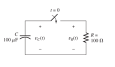
Figure P4.11
Expert Solution & Answer

Trending nowThis is a popular solution!

Students have asked these similar questions
HW_03.pdf EE 213-01 > Assignments
HW_#3
uah.instructure.com
b Success Confirmation of Question Submission | bartleby
✓ Download
→ Info
× Close
Page
1
>
of 2
-
ZOOM +
1) (5 pts) Use node voltage analysis at nodes A and B to determine values for VA, VB, I₁, 12 and 13.
If a current has a negative value, then the reference direction chosen was incorrect and the current
is positive in the opposite direction. Your answer can be the negative value – i.e. you find that 12 =
-1mA. Note, the current through R5 is (VB - 28 Volts)/10K
10K VA
20K VB
10K
R1
12
R2
R5
13
IS1
R3
10 mA
10K
28 V
R4
VS1
5K
-VREF
B
2) (5pts) Use node voltage analysis to find values for the node voltages VA, VR and Vc. Use these
node voltages to determine values for V1, V2, V3, V4, 11, 12, 13, and 14. Hints: V3 = VB and the value
for Vc can be found with no analysis. Dependent current source has a value of gV3 amps
VA
gV3 Amps
14
12
20K
+
V2
-
+
10K
VB
13
V3 10K
-
20K
I₁
V₁ +
Vc
g=5x10⁻⁵
20 volts
VREF
3) (5 pts) For the…
HW_02.pdf EE 213-01 > Assignments
HW_#4
uah.instructure.com
b Success Confirmation of Question Submission | bartleby
✓ Download
→ Info
× Close
1) (5 pts)For the circuit shown, find the value of Ia, Ib, I¸ and Va:
Ib
10 Ohms
+
Ic
20 Ohms
70 Volts
Va
40 Ohms
Page
1
>
of 2
-
ZOOM +
Hint: use KCL to find Ic in terms of la and lb, use KVL around the right loop to find a relationship
between la and lb, use KVL around the outer loop to solve for a current value (use ohms law for
the voltage drops across the resistors)
-
2) (5 pts) For problem 1, show that the power supplied (delivered) by the source equals the
power absorbed by the resistors.
3) (5 pts) Determine the equivalent resistance looking into terminals a-b for the two circuits
shown. Use series and parallel resistor combinations. Hint: work from the opposite end of
terminals a-b towards terminals a-b
a)
24 Ohms
10 Ohms
8 Ohms
a
REQ
b)
b =
75K
5 Ohms
50K
60 Ohms
4 OHMs
20 Ohms
30 Ohms
□ a
20K
8.2K
40K
16K
10K
□ b
7.2K
REQ
Make a LTSpice draws for the design below
Chapter 4 Solutions
Electrical Engineering: Principles & Applications, 7th Edition
Ch. 4 - Suppose we have a capacitance C discharging...Ch. 4 - The dielectric materials used in real capacitors...Ch. 4 - The initial voltage across the capacitor shown in...Ch. 4 - A 100F capacitance is initially charged to 1000 V....Ch. 4 - At t = 0, a charged 10{ F capacitance is connected...Ch. 4 - At time t1 , a capacitance C is charged to a...Ch. 4 - Given an initially charged capacitance that begins...Ch. 4 - The initial voltage across the capacitor shown in...Ch. 4 - In physics, the half-life is often used to...Ch. 4 - We know that a 50F capacitance is charged to an...
Ch. 4 - We know that the capacitor shown in Figure P4.11...Ch. 4 - The purchasing power P of a certain unit of...Ch. 4 - Derive an expression for vC(t) in the circuit of...Ch. 4 - Suppose that at t= 0, we connect an uncharged 10 F...Ch. 4 - Suppose we have a capacitance C that is charged to...Ch. 4 - A person shuffling across a dry carpet can be...Ch. 4 - Prob. 4.17PCh. 4 - Consider the circuit shown in Figure P4.18. Prior...Ch. 4 - List the steps for dc steady-state analysis of RLC...Ch. 4 - Explain why we replace capacitances with open...Ch. 4 - Solve for the steady-state values of i1, i2, and...Ch. 4 - Consider the circuit shown in Figure P4.22. What...Ch. 4 - In the circuit of Figure P4.23, the switch is in...Ch. 4 - The circuit shown in Figure P4.24 has been set up...Ch. 4 - Solve for the steady-state values of i1 , i2, i3,...Ch. 4 - The circuit shown in Figure P4.26 is operating in...Ch. 4 - Prob. 4.27PCh. 4 - Consider the circuit of Figure P4.28 in which the...Ch. 4 - For the circuit shown in Figure P4.29, the switch...Ch. 4 - Consider the circuit of Figure P4.30 in which the...Ch. 4 - Give the expression for the time constant of a...Ch. 4 - A circuit consists of switches that open or close...Ch. 4 - The circuit shown in Figure P4.33 is operating in...Ch. 4 - Consider the circuit shown in Figure P4.34. The...Ch. 4 - Repeat Problem P4.34 given iL(0)=0A .Ch. 4 - Real inductors have series resistance associated...Ch. 4 - Determine expressions for and sketch is(t) to...Ch. 4 - For the circuit shown in Figure P4.38,, find an...Ch. 4 - The circuit shown in Figure P4.39 is operating in...Ch. 4 - Consider the circuit shown in Figure P4.40. A...Ch. 4 - Due to components not shown in the figure, the...Ch. 4 - The switch shown in Figure P4.42 has been closed...Ch. 4 - Determine expressions for and sketch vR(t) to...Ch. 4 - What are the steps in solving a circuit having a...Ch. 4 - Prob. 4.45PCh. 4 - Solve for vC(t) for t > 0 in the circuit of Figure...Ch. 4 - Solve for v(t) for t > 0 in the circuit of Figure...Ch. 4 - Prob. 4.48PCh. 4 - Consider the circuit shown inFigure P4.49. The...Ch. 4 - Consider the circuit shown in Figure P4.50. The...Ch. 4 - The voltage source shown in Figure P4.51 is called...Ch. 4 - Determine the form of the particular solution for...Ch. 4 - Determine the form of the particular solution for...Ch. 4 - Prob. 4.54PCh. 4 - Prob. 4.55PCh. 4 - How can first-or second-order circuits be...Ch. 4 - Prob. 4.57PCh. 4 - Prob. 4.58PCh. 4 - Prob. 4.59PCh. 4 - Sketch a step response for a second-order system...Ch. 4 - A dc source is connected to a series RLC circuit...Ch. 4 - Repeat Problem P4.61 for R = 40 .Ch. 4 - Repeat Problem P4.61 for R = 20 .Ch. 4 - Prob. 4.64PCh. 4 - Repeat Problem P4.64 for R=50 .Ch. 4 - Repeat Problem P4.64 for R=500 .Ch. 4 - Solve for i(t) for t > 0 in the circuit of Figure...Ch. 4 - Prob. 4.68PCh. 4 - Prob. 4.69PCh. 4 - Prob. 4.70PCh. 4 - Use MATLAB to derive an expression for vc(t)in the...Ch. 4 - Prob. 4.72PCh. 4 - Consider the circuit shown in FigureP4.50 in which...Ch. 4 - Prob. 4.74PCh. 4 - Prob. 4.75PCh. 4 - Use MATLAB to solve for the mesh currents in the...Ch. 4 - The switch m the circuit shown in Figure T4.1 is...Ch. 4 - Prob. 4.2PTCh. 4 - Consider the circuit shown in Figure T4.3. Figure...Ch. 4 - Consider the circuit shown in Figure T4.4 in which...Ch. 4 - Write the MATLAB commands to obtain the solution...
Additional Engineering Textbook Solutions
Find more solutions based on key concepts
What is the importance of modeling in engineering? How are the mathematical models for engineering processes pr...
HEAT+MASS TRANSFER:FUND.+APPL.
This optional Google account security feature sends you a message with a code that you must enter, in addition ...
SURVEY OF OPERATING SYSTEMS
The job of the _____ is to fetch instructions, carry out the operations commanded by the instructions, and prod...
Starting Out With Visual Basic (8th Edition)
Why is the study of database technology important?
Database Concepts (8th Edition)
Assume a telephone signal travels through a cable at two-thirds the speed of light. How long does it take the s...
Electric Circuits. (11th Edition)
17–1C A high-speed aircraft is cruising in still air. How does the temperature of air at the nose of the aircra...
Thermodynamics: An Engineering Approach
Knowledge Booster


Learn more about
Need a deep-dive on the concept behind this application? Look no further. Learn more about this topic, electrical-engineering and related others by exploring similar questions and additional content below.Similar questions
- A student organization has 12 members. A committee of 5members needs to be selected. How many ways can the committee be formed?arrow_forwardA fair coin is flipped 10 times. What is the probability that the coin lands on heads exactly 6 times?arrow_forwardA machine produces screws, and each screw has a 10% chance of being defective. A customer orders a batch of 25 screws. What is the probability that no more than 2 screws are defective in the batch?arrow_forward
- Q29arrow_forward1. Consider a pendulum consisting of two point masses on a single rod as shown below. The external torque acting on the pendulum is u(t). Suppose, the damping coefficient of the frictional toque is b. Find the nonlinear differential equation for the pendulum angle 0. marrow_forward4. Consider the following fluid system consisting of two tanks. Bult) Assume, R = 10, p = 1, g = 10 and ẞ = 1. a) Find the differential equation of the system. b) Find the transfer function (s) U(s)arrow_forward
arrow_back_ios
SEE MORE QUESTIONS
arrow_forward_ios
Recommended textbooks for you
 Introductory Circuit Analysis (13th Edition)Electrical EngineeringISBN:9780133923605Author:Robert L. BoylestadPublisher:PEARSON
 Delmar's Standard Textbook Of ElectricityElectrical EngineeringISBN:9781337900348Author:Stephen L. HermanPublisher:Cengage Learning
 Programmable Logic ControllersElectrical EngineeringISBN:9780073373843Author:Frank D. PetruzellaPublisher:McGraw-Hill Education
 Fundamentals of Electric CircuitsElectrical EngineeringISBN:9780078028229Author:Charles K Alexander, Matthew SadikuPublisher:McGraw-Hill Education
 Electric Circuits. (11th Edition)Electrical EngineeringISBN:9780134746968Author:James W. Nilsson, Susan RiedelPublisher:PEARSON
 Engineering ElectromagneticsElectrical EngineeringISBN:9780078028151Author:Hayt, William H. (william Hart), Jr, BUCK, John A.Publisher:Mcgraw-hill Education,
Introductory Circuit Analysis (13th Edition)
Electrical Engineering
ISBN:9780133923605
Author:Robert L. Boylestad
Publisher:PEARSON
Delmar's Standard Textbook Of Electricity
Electrical Engineering
ISBN:9781337900348
Author:Stephen L. Herman
Publisher:Cengage Learning
Programmable Logic Controllers
Electrical Engineering
ISBN:9780073373843
Author:Frank D. Petruzella
Publisher:McGraw-Hill Education
Fundamentals of Electric Circuits
Electrical Engineering
ISBN:9780078028229
Author:Charles K Alexander, Matthew Sadiku
Publisher:McGraw-Hill Education
Electric Circuits. (11th Edition)
Electrical Engineering
ISBN:9780134746968
Author:James W. Nilsson, Susan Riedel
Publisher:PEARSON
Engineering Electromagnetics
Electrical Engineering
ISBN:9780078028151
Author:Hayt, William H. (william Hart), Jr, BUCK, John A.
Publisher:Mcgraw-hill Education,
Capacitors Explained - The basics how capacitors work working principle; Author: The Engineering Mindset;https://www.youtube.com/watch?v=X4EUwTwZ110;License: Standard YouTube License, CC-BY