
Concept explainers
(a)
The free body diagram of the shaft.
The reactions at
(a)
Answer to Problem 75P
The free body-diagram of the shaft is as follows.

The reaction at
Explanation of Solution
The figure below shows the arrangement of shafts.
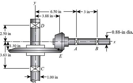
Figure (1)
The free body diagram of the shafts is shown below.
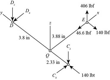
Figure (2)
Write the expression of moment at
Here, the reaction at
Write the expression of moment at
Here, the reaction at
Write the expression of moment at
Here, the reaction at
Write the expression of moment at
Write the expression of net force at
Here, the reaction at
Conclusion:
Substitute
Thus, the reaction at
Substitute
Thus, the reaction at
Substitute
Thus, the reaction at
Substitute
Thus, the reaction at
Substitute
Thus, the reaction at
(b)
The shear force and bending moment diagrams.
(b)
Answer to Problem 75P
The figure below shows the shear force and bending moment diagram in

The figure below shows the shear force and bending moment diagram in
Explanation of Solution
It is clear from the free body diagram of the shaft
The calculations for shear force diagram in
Write the expression of Shear force at
Here, the shear at
Write the expression of Shear force at
Here, the shear force at
Write the expression of Shear force at
Here, the shear force at
The calculations for bending moment diagram in
We known that, the bending moment at the supports of the simply supported beam is zero.
Write the bending moment at
Here, the bending moment at
Write the expression of bending moment at
Here, the bending moment at
Write the expression of bending moment at
Here, the bending moment at
The calculations for shear force diagram in
Write the expression of Shear force at
Here, the shear at
Write the expression of Shear force at
Here, the shear force at
Write the expression of Shear force at
Here, the shear force at
We known that, the bending moment at the supports of the simply supported beam is zero.
Write the bending moment at
Here, the bending moment at
Write the expression of bending moment at
Here, the bending moment at
Conclusion:
Substitute
Substitute
Substitute
Substitute
Substitute
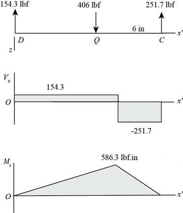
The figure below shows the shear force and bending moment diagram in
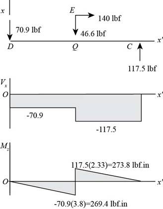
Figure (3)
Substitute
Substitute
Substitute
Substitute
The figure below shows the shear force and bending moment diagram in
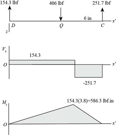
Figure (4)
(c)
The torsional shear stress for critical stress element.
The bending stress for critical stress element.
The axial stress for critical stress element.
(c)
Answer to Problem 75P
The torsional shear stress for critical stress element is
The bending stress for critical stress element is
The axial stress for critical stress element is
Explanation of Solution
It is clear from the bending moment diagram that the critical stress element is located at just right of
Write the expression of maximum torque acting on the shaft
Here, the maximum torque acting on the shaft
Write the expression of maximum bending moment acting on the shaft
Here, the maximum bending moment acting on the shaft
Write the expression of torsional shear stress for critical stress element.
Here, the torsional shear stress for critical stress element is
Write the expression of bending stress for critical stress element.
Here, the bending stress for critical stress element is
Write the expression of axial stress for critical stress element.
Here, the axial stress for critical stress element is
Conclusion:
Substitute
Substitute
Substitute
Thus, the torsional shear stress for critical stress element is
Substitute
Thus, the bending stress for critical stress element is
Substitute
Thus, the axial stress for critical stress element is
(d)
The principal stresses for critical stress element.
The maximum shear stress for critical stress element.
(d)
Answer to Problem 75P
The principal stresses for critical stress element are
The maximum shear stress for critical stress element is
Explanation of Solution
Write the expression of maximum bending stress on the critical stress element.
Here, the maximum bending stress on the critical stress element is
Write the expression of principal stresses on the critical stress element.
Here, the principal stresses on the critical stress element are
Write the expression of maximum shear stress on the critical stress element.
Here, the maximum shear stress on the critical stress element is
Conclusion:
Substitute
Substitute
Thus, the principal stresses for critical stress element are
Substitute
Thus, the maximum shear stress for critical stress element is
Want to see more full solutions like this?
Chapter 3 Solutions
Shigley's Mechanical Engineering Design (McGraw-Hill Series in Mechanical Engineering)


- The problems are generally based on the following model: A particular spacecraft can be represented as a single axisymmetric rigid body B. Let n₂ be inertially fixed unit vectors; then, 6, are parallel to central, principal axes. To make the mathematics simpler, introduce a frame C where n₂ = ĉ₁ = b; initially. 6₁ Assume a mass distribution such that J =₁₁• B* •b₁ = 450 kg - m² I = b² •Ï¾˜ • b₂ = b¸ •Ï¾* •b¸ = 200 kg - m² K J-I C³ =r₁₁ = r₁₁arrow_forward##### Determine an example of a design of a compressed air system, which uses the criterion of speed for the design of the pipes (formula attached). The demands of flow rate, power as well as air velocity in the pipelines can be freely chosen. Sizing the compressor (flow, power...) Size reservoir required Setting the dryer Determine the amount of water withdrawn from the system due to air compression **With the attached formula you can choose the appropriate values of the unknownsarrow_forwardTo make an introduction to a report of a simple design of a compressed air system, which uses the criterion of speed, and not that of pressure drop, to determine the diameter of the pipes, where the capacity of the compressor and the demands of the equipment are expressed in flow.arrow_forward
- In an irrigation system, the following characteristics of the pipe network are available.• 100 meters of 4" PVC pipe, 3 gate valves• 500 meters of 3" PVC pipe, 4 gate valves• 200 meters of 2" H.G. pipe, 2 globe valves• 50 litres per second circulate in the pipes:Calculate:1. Total energy losses in meters.2. Leaks in pipes.3. Losses in accessories.4. Calculate the equivalent pipe of that system assuming only pipes without fittings.Solve the problem without artificial intelligence, solve by one of the expertsarrow_forwardLiquid water enters the boiler at 60 bar. Steam exits the boiler at 60 bar, 540°C and undergoes a throttling process to 40 bar before entering the turbine. Steam expands adiabatically through the turbine to 5 bar, 240°C, and then undergoes a throttling process to 1 bar before entering the condenser. Kinetic and potential energy effects can be ignored. Draw a Temperature-Entropy diagram and mark each of the states 2-5 on this diagram. Determine the power generated by the turbine, in kJ per kg of steam flowing. For the valves and the turbine, evaluate the rate of entropy production, each in kJ/K per kg of steam flowing.arrow_forwardFind the componenets of reactions at pins of A, B and D please show the detailed process and instructions for learning draw out all diagrams please and thank youarrow_forward
- A cast iron cylinder of 200 mm inner diameter and 12.5 mm thick is closely wound with a layer of 4 mm diameter steel wire under a tensile stress of 55 MN/m². Determine the stresses set up in the cylinder and steel wire if water under a pressure of 3 MN/m² is admitted in the cylinder. Take E= 100 GN/m², E = 200 GN/m² and Poisson's ratio = 0.25.arrow_forwardWhat is the effect of a clogged fuel injector?arrow_forwardYou are asked to design a unit to condense ammonia. The required condensation rate is 0.09kg/s. Saturated ammonia at 30 o C is passed over a vertical plate (10 cm high and 25 cm wide).The properties of ammonia at the saturation temperature of 30°C are hfg = 1144 ́10^3 J/kg andrho_v = 9.055 kg/m 3 . Use the properties of liquid ammonia at the film temperature of 20°C (Ts =10 o C):Pr = 1.463 rho_l= 610.2 kf/m^3 liquid viscosity= 1.519*10^-4 kg/ ms kinematic viscosity= 2.489*10^-7 m^2/s Cpl= 4745 J/kg C kl=0.4927 W/m C hfg*=hfg+0.68Cpl(Tsat-Given Ts) a) Instead of one plate you want to use small plates and install many of them. Calculate the requiredsurface temperature to achieve the desired condensation rate (0.09 kg/s) if you install 36vertical plates (with the same dimension as above: 10 cm high and 25 cm wide).arrow_forward
- 11-19 designed in Problem The shaft shown in figure P11-4 was 10-19, for the data in the row(s) assigned from table PII-1, and the corresponding diameter of shaft found in Problem 10-19, design suitable bearings 5 E8 cycles at the load for at least State all assumptions. to support 1200rpm. (a) Using hydrodynamically lubricated bronze sleeve bearings with ON = 40, Lld = 0.8, and clearance ratio 0.0025. of a ← gear T gear Key figure PI-4 Given from the problem 10-19 we get d= 1.153 in from the table 11-1 we get a = 16 in b= 18in L= 20inarrow_forwardIn an irrigation system, the following characteristics of the pipe network are available.• 100 meters of 4" PVC pipe, 3 gate valves• 500 meters of 3" PVC pipe, 4 gate valves• 200 meters of 2" H.G. pipe, 2 globe valves• 50 litres per second circulate in the pipes:Calculate:1. Total energy losses in meters.2. Leaks in pipes.3. Losses in accessories.4. Calculate the equivalent pipe of that system assuming only pipes without fittings.Solve the problem without artificial intelligence, solve by one of the expertsarrow_forwardIn a series pipe, calculate the diameter 2 according to the following:• Ltotal: 325 m• L1: 52 m, D1: 3/4"• L2: 254 m, D2:?• L3: 19 m, D: 1-1/4".Indicate the nominal diameter. Solve without using artificial inteligence, solve by one of the expertsarrow_forward
 Mechanics of Materials (MindTap Course List)Mechanical EngineeringISBN:9781337093347Author:Barry J. Goodno, James M. GerePublisher:Cengage Learning