
Concept explainers
Videos
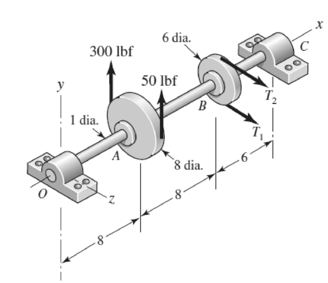
3-68* to 3-71* A countershaft two V-belt pulleys is shown in the figure. Pulley A receives power from a motor through a belt with the belt tensions shown. The power is transmitted through the shaft and delivered to the belt on pulley B. Assume the belt tension on the loose side at B is 15 percent of the tension on the tight side.
- (a) Determine the tensions in the belt on pulley B, assuming the shaft is running at a constant speed.
- (b) Find the magnitudes of the bearing reaction forces, assuming the bearings act as simple supports.
- (c) Draw shear-force and bending-moment diagrams for the shaft. If needed, make one set for the horizontal plane and another set for the vertical plane.
- (d) At the point of maximum bending moment, determine the bending stress and the torsional shear stress.
- (e) At the point of maximum bending moment, determine the principal stresses and the maximum shear stress.
Problem 3-70*
Dimensions in inches.
(a)
The tensions in the belt of pulley
Answer to Problem 70P
The tension in the belt pulley
Explanation of Solution
The Free body diagram of pulley
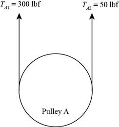
Figure (1)
The free body diagram of pulley
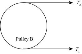
Figure (2)
The given assumption is that the belt tension on the loose side at
Write the relationship between tension on the loose side with respect to tension on the tight side.
Here, the tension on the tight side is
Write the equation to balance the tension on the counter shaft.
Here, the tension on the tight side of pulley
Substitute
Calculate the tension on the loose side.
Conclusion:
Substitute
Thus, the tension in the belt of pulley
Substitute
Thus, the tension in the belt of pulley
(b)
The magnitude of the bearing reaction forces.
Answer to Problem 70P
The magnitude of bearing reaction force at
Explanation of Solution
Write the magnitude of bearing reaction force at
Here, the magnitude of the bearing force at
Write the magnitude of bearing reaction force at
Write the magnitude of bearing reaction force at
Here, the magnitude of bearing force at
Write the magnitude of bearing force at
Here, the magnitude of bearing reaction force at
Calculate the bearing reaction force at
Here, the bearing reaction force at
Calculate the bearing reaction force at
Here, the bearing reaction force at
Conclusion:
Substitute
Substitute
Substitute
Substitute
Substitute
Substitute
Thus, the magnitude of bearing reaction force at
(c)
The shear force diagram and bending moment diagram for the shaft.
Answer to Problem 70P
The shear force diagram and bending moment diagram for the shaft in
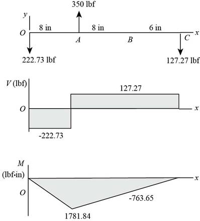
The shear force diagram and bending moment diagram for the shaft in
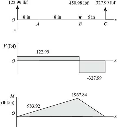
Explanation of Solution
The calculations for shear force and bending moment diagram in
Calculate the shear force at
Here, the shear force at
Calculate the shear force at
Here, the shear force at
Calculate the shear force at
Here, the shear force at
Calculate the moment at
The moment at the supports of the simply supported beam is zero.
Calculate the moment at
Here, the moment at
Calculate the moment at
Here, the moment at
Conclusion:
Substitute
Substitute
Substitute
Substitute
Substitute
Thus, the shear force diagram and bending moment diagram for the shaft in

Figure (3)
Substitute
Substitute
Substitute
Substitute
Substitute
Thus, the shear force diagram and bending moment diagram for the shaft in

Figure (4)
(d)
The bending stress at point of maximum bending moment.
The shear stress at point of maximum bending moment.
Answer to Problem 70P
The bending stress at point of maximum bending moment is
The shear stress at point of maximum bending moment is
Explanation of Solution
Write the net moment at
Here, the net moment at
Write the net moment at
Here, the net moment at
Write the torque transmitted by shaft from
Here, the torque transmitted by shaft from
Calculate the bending stress.
Here, the bending stress is
Calculate the shear stress.
Here, the shear stress is
Conclusion:
Substitute
Substitute
Since,
Substitute
Substitute
Thus, the bending stress at point of maximum bending moment is
Substitute
Thus, the shear stress at point of maximum bending moment is
(e)
The principal stresses at point of maximum bending moment.
The maximum shear stress at point of maximum bending moment.
Answer to Problem 70P
The principal stresses at point of maximum bending moment are
The maximum shear stress at point of maximum bending moment is
Explanation of Solution
Calculate the maximum principal stress.
Here, the maximum principal stress is
Calculate the minimum principal stress.
Here, the minimum principal stress is
Calculate the maximum shear stress.
Here, maximum shear stress is
Conclusion:
Substitute
Substitute
Thus, the principal stresses at point of maximum bending moment are
Substitute
Thus, the maximum shear stress at point of maximum bending moment is
Want to see more full solutions like this?
Chapter 3 Solutions
Shigley's Mechanical Engineering Design (McGraw-Hill Series in Mechanical Engineering)


- (Read image)arrow_forward(Read Image)arrow_forwardM16x2 grade 8.8 bolts No. 25 C1- Q.2. The figure is a cross section of a grade 25 cast-iron pressure vessel. A total of N, M16x2.0 grade 8.8 bolts are to be used to resist a separating force of 160 kN. (a) Determine ks, km, and C. (b) Find the number of bolts required for a load factor of 2 where the bolts may be reused when the joint 19 mm is taken apart. (c) with the number of bolts obtained in (b), determine the realized load factor for overload, the yielding factor of safety, and the separation factor of safety. 19 mmarrow_forward
- Problem4. The thin uniform disk of mass m = 1-kg and radius R = 0.1m spins about the bent shaft OG with the angular speed w2 = 20 rad/s. At the same time, the shaft rotates about the z-axis with the angular speed 001 = 10 rad/s. The angle between the bent portion of the shaft and the z-axis is ẞ = 35°. The mass of the shaft is negligible compared to the mass of the disk. a. Find the angular momentum of the disk with respect to point G, based on the axis orientation as shown. Include an MVD in your solution. b. Find the angular momentum of the disk with respect to point O, based on the axis orientation as shown. (Note: O is NOT the center of fixed-point rotation.) c. Find the kinetic energy of the assembly. z R R 002 2R x Answer: H = -0.046ĵ-0.040 kg-m²/sec Ho=-0.146-0.015 kg-m²/sec T 0.518 N-m =arrow_forwardProblem 3. The assembly shown consists of a solid sphere of mass m and the uniform slender rod of the same mass, both of which are welded to the shaft. The assembly is rotating with angular velocity w at a particular moment. Find the angular momentum with respect to point O, in terms of the axes shown. Answer: Ñ。 = ½mc²wcosßsinßĵ + (}{mr²w + 2mb²w + ½ mc²wcos²ß) k 3 m r b 2 C لا marrow_forwardOnly question 2arrow_forward
- Only question 1arrow_forwardOnly question 3arrow_forwardI have Euler parameters that describe the orientation of N relative to Q, e = -0.7071*n3, e4 = 0.7071. I have Euler parameters that describe the orientation of U relative to N, e = -1/sqrt(3)*n1, e4 = sqrt(2/3). After using euler parameter rule of successive rotations, I get euler parameters that describe the orientation of U relative to Q, e = -0.4082*n1 - 0.4082*n2 - 0.5774*n3. I need euler parameters that describe the orientation of U relative to Q in vector basis of q instead of n. How do I get that?arrow_forward
- Describe at least 4 processes in engineering where control charts are (or should be) appliedarrow_forwardDescribe at least two (2) processes where control charts are (or should be) applied.arrow_forwardProblem 3: A cube-shaped spacecraft is in a circular Earth orbit. Let N (n,) be inertial and the spacecraft is denoted S (ŝ₁). The spacecraft is described such that ¯½º = J ŝ₁ŝ₁ + J ŝ₂§₂ + J §¸Ŝ3 Location of the spacecraft in the orbit is determined by the orbit-fixed unit vectors ê, that are oriented by the angle (Qt), where is a constant angular rate. 52 €3 3> 2t 55 Λ Из At the instant when Qt = 90°, the spacecraft S is oriented relative to the orbit such that 8₁ = 0° Space-three 1-2-3 angles 0₂ = 60° and ES = $₂ rad/s 0₁ = 135° (a) At this instant, determine the direction cosine matrix that describes the orientation of the spacecraft with respect to the inertial frame N.arrow_forward
 Mechanics of Materials (MindTap Course List)Mechanical EngineeringISBN:9781337093347Author:Barry J. Goodno, James M. GerePublisher:Cengage Learning