For the knuckle joint described in Prob. 3-40, assume the maximum allowable tensile stress in the pin is 30 kpsi and the maximum allowable shearing stress in the pin is 15 kpsi. Use the model shown in part c of the figure to determine a minimum pin diameter for each of the following potential failure modes. (a) Consider failure based on bending at the point of maximum bending stress in the pin. (b) Consider failure based on the average shear stress on the pin cross section at the interface plane of the knuckle and clevis. (c) Consider failure based on shear at the point of the maximum transverse shear stress in the pin. 3-40* A pin in a knuckle joint canning a tensile load F deflects somewhat on account of this loading, making the distribution of reaction and load as shown in part ( b ) of the figure. A common simplification is to assume uniform load distributions, as shown in part ( c ). To further simplify, designers may consider replacing the distributed loads with point loads, such as in the two models shown in parts d and e . If a = 0.5 in. b = 0.75 in. d = 0.5 in. and F = 1000 lbf, estimate the maximum bending stress and the maximum shear stress due to V for the three simplified models. Compare the three models from a designer's perspective in terms of accuracy, safely, and modeling time. Problem 3-40*
For the knuckle joint described in Prob. 3-40, assume the maximum allowable tensile stress in the pin is 30 kpsi and the maximum allowable shearing stress in the pin is 15 kpsi. Use the model shown in part c of the figure to determine a minimum pin diameter for each of the following potential failure modes. (a) Consider failure based on bending at the point of maximum bending stress in the pin. (b) Consider failure based on the average shear stress on the pin cross section at the interface plane of the knuckle and clevis. (c) Consider failure based on shear at the point of the maximum transverse shear stress in the pin. 3-40* A pin in a knuckle joint canning a tensile load F deflects somewhat on account of this loading, making the distribution of reaction and load as shown in part ( b ) of the figure. A common simplification is to assume uniform load distributions, as shown in part ( c ). To further simplify, designers may consider replacing the distributed loads with point loads, such as in the two models shown in parts d and e . If a = 0.5 in. b = 0.75 in. d = 0.5 in. and F = 1000 lbf, estimate the maximum bending stress and the maximum shear stress due to V for the three simplified models. Compare the three models from a designer's perspective in terms of accuracy, safely, and modeling time. Problem 3-40*
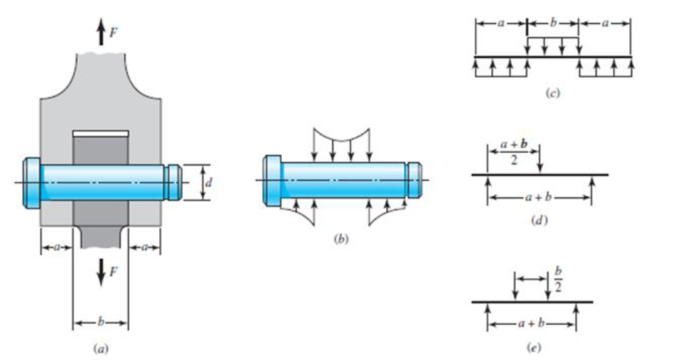
Solution Summary: The following figure shows the free body diagram of the forces on the model (c).
For the knuckle joint described in Prob. 3-40, assume the maximum allowable tensile stress in the pin is 30 kpsi and the maximum allowable shearing stress in the pin is 15 kpsi. Use the model shown in part c of the figure to determine a minimum pin diameter for each of the following potential failure modes.
(a) Consider failure based on bending at the point of maximum bending stress in the pin.
(b) Consider failure based on the average shear stress on the pin cross section at the interface plane of the knuckle and clevis.
(c) Consider failure based on shear at the point of the maximum transverse shear stress in the pin.
3-40* A pin in a knuckle joint canning a tensile load F deflects somewhat on account of this loading, making the distribution of reaction and load as shown in part (b) of the figure. A common simplification is to assume uniform load distributions, as shown in part (c). To further simplify, designers may consider replacing the distributed loads with point loads, such as in the two models shown in parts d and e. If a = 0.5 in. b = 0.75 in. d = 0.5 in. and F = 1000 lbf, estimate the maximum bending stress and the maximum shear stress due to V for the three simplified models. Compare the three models from a designer's perspective in terms of accuracy, safely, and modeling time.
F1
3
5
4 P
F2
F2
Ꮎ
Ꮎ
b
P
3
4
5
F1
The electric pole is subject to the forces shown. Force F1
245 N and force F2 = 310 N with an angle
= 20.2°.
Determine the moment about point P of all forces. Take
counterclockwise moments to be positive.
=
Values for dimensions on the figure are given in the following
table. Note the figure may not be to scale.
Variable Value
a
2.50 m
b
11.3 m
C
13.0 m
The moment about point P is 3,414
m.
× N-
If the moment about point P sums up to be zero. Determine
the distance c while all other values remained the same.
1.26
m.
Z
0.2 m
B
PROBLEM 15.224
Rod AB is welded to the 0.3-m-radius plate, which rotates at the
constant rate ₁ = 6 rad/s. Knowing that collar D moves toward end B
of the rod at a constant speed u = 1.3 m, determine, for the position
shown, (a) the velocity of D, (b) the acceleration of D.
Answers: 1.2 +0.5-1.2k m/s
a=-7.21-14.4k m/s²
A
0.25 m
0.3 m
I am trying to code in MATLAB the equations of motion for malankovich orbitlal elements. But, I am having a problem with the B matrix. Since f matrix is 7x1 and a_d matrix has to be 3x1, the B matrix has to be 7x3. I don't know how that is possible. Can you break down the B matrix for me and let me know what size it is?
Chapter 3 Solutions
Shigley's Mechanical Engineering Design (McGraw-Hill Series in Mechanical Engineering)
Need a deep-dive on the concept behind this application? Look no further. Learn more about this topic, mechanical-engineering and related others by exploring similar questions and additional content below.
Everything About COMBINED LOADING in 10 Minutes! Mechanics of Materials; Author: Less Boring Lectures;https://www.youtube.com/watch?v=N-PlI900hSg;License: Standard youtube license


 Mechanics of Materials (MindTap Course List)Mechanical EngineeringISBN:9781337093347Author:Barry J. Goodno, James M. GerePublisher:Cengage Learning