
Concept explainers
Videos
For each of the plane stress states listed below, draw a Mohr’s circle diagram properly labeled, find the principal normal and shear stresses, and determine the angle from the x axis to σ1. Draw stress elements as in Fig. 3–11c and d and label all details.
(a) σx = 20 kpsi, σy = 210 kpsi, τxy = 8 kpsi cw
(b) σx = 16 kpsi, σy = 9 kpsi, τxy = 5 kpsi ccw
(c) σx = 10 kpsi, σy = 24 kpsi, τxy = 6 kpsi ccw
(d) σx = 212 kpsi, σy = 22 kpsi, τxy = 12 kpsi cw
(a)
The principle normal stress.
The shear stress.
The angle from
Answer to Problem 15P
The principle normal stress
The shear stress is
The angle from
Explanation of Solution
The Figure (1) shows the state of stress on the element for
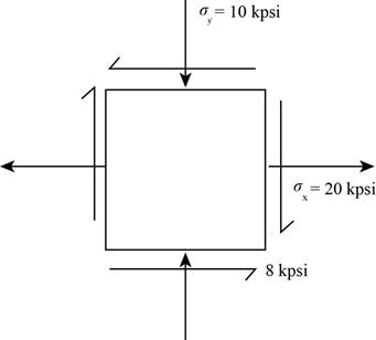
Figure (1)
Write the coordinates of the points through which the Mohr’s circle pass.
Here, the stress along x face is
Draw the
Write the formula for the center point.
Here, the center point is
Write the expression for the angle between the line joining points A and B with
Here, the angle made by the diameter with positive x-axis in the counterclockwise direction is
Write the expression of the radius of circle.
Write the expression maximum in plane normal stress.
Here, the maximum in plane normal stress are
Write the expression of maximum in plane shear stress.
Here, the maximum shear stress is
Write the expression for the angle of maximum shear plane.
Here, the angle is
Conclusion:
Substitute
Draw the Mohr’s circle diagram.
The Figure (2) shows the Mohr’s circle diagram.
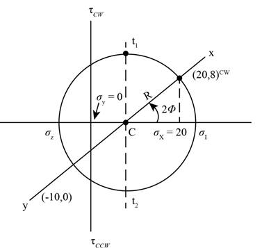
Figure (2)
Substitute the value
Substitute the value
Substitute
Substitute
Thus, the principle normal stress
Substitute
Thus, the maximum shear stress is
Substitute the value
Thus, the angle from
The Figure (3) shows the maximum in plane normal stress distribution about the plane.
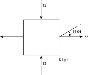
Figure (3)
The Figure (4) shows stress distribution at maximum shear stress plane.
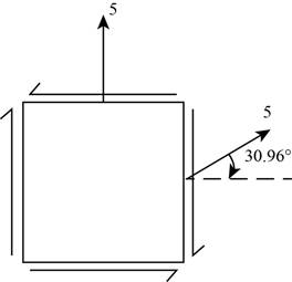
Figure (4)
(b)
The principle normal stress.
The shear stress.
The angle from
Answer to Problem 15P
The principle normal stress
The shear stress is
The angle from
Explanation of Solution
The Figure (5) shows the state of stress on the element for
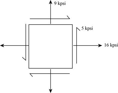
Figure (5)
Conclusion:
Substitute the value
Draw the Mohr’s circle diagram.
The Figure (2) shows the Mohr’s circle diagram.
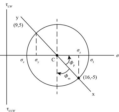
Figure (6)
Substitute the value
Substitute the value
Substitute the value
Substitute the value
Thus, the principle normal stress
Substitute the value
Thus, the maximum shear stress is
Substitute
Thus, the angle from
The Figure (3) shows the maximum in plane normal stress distribution about the plane.
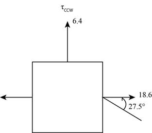
Figure (7)
The Figure (4) shows stress distribution at maximum shear stress plane.
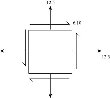
Figure (8)
(c)
The principle normal stress.
The shear stress.
The angle from
Answer to Problem 15P
The principle normal stress
The shear stress is
The angle from
Explanation of Solution
The Figure (5) shows the state of stress on the element for
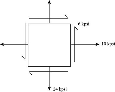
Figure (9)
Conclusion:
Substitute the value
Draw the Mohr’s circle diagram.
The Figure (2) shows the Mohr’s circle diagram.
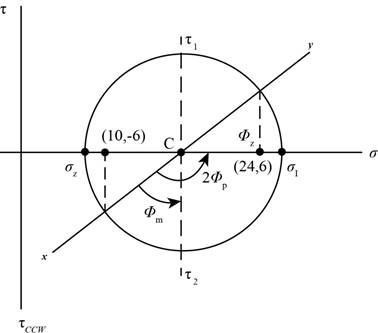
Figure (10)
Substitute the value
Substitute the value
Write the value of
Substitute the value
Substitute the value
Thus, the principle normal stress
Substitute
Thus, the maximum shear stress is
Substitute the value
Thus, the angle from
The Figure (3) shows the maximum in plane normal stress distribution about the plane.
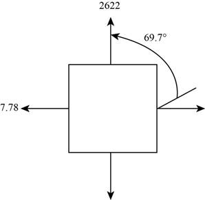
Figure (11)
The Figure (4) shows stress distribution at maximum shear stress plane.
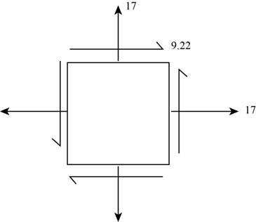
Figure (12)
(d)
The principle normal stress.
The shear stress.
The angle from
Answer to Problem 15P
The principle normal stress
The shear stress is
The angle from
Explanation of Solution
The Figure (5) shows the state of stress on the element for
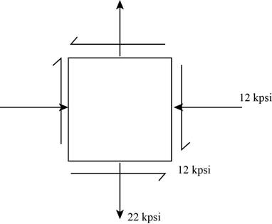
Figure (13)
Conclusion:
Substitute the value
Draw the Mohr’s circle diagram.
The Figure (2) shows the Mohr’s circle diagram.
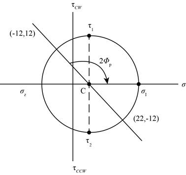
Figure (14)
Substitute the value for
Substitute the value
Write the value of
Substitute the value
Substitute the value
Thus, the principle normal stress
Substitute the value
Thus, the shear stress is
Substitute the value
Thus, the angle from
The Figure (3) shows the maximum in plane normal stress distribution about the plane.
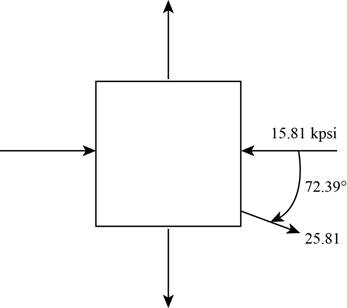
Figure (15)
The Figure (4) shows stress distribution at maximum shear stress plane.
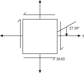
Figure (16)
Want to see more full solutions like this?
Chapter 3 Solutions
Shigley's Mechanical Engineering Design (McGraw-Hill Series in Mechanical Engineering)


- 3. A steam power plant has an average monthly net power delivery of 740 MW over the course of a year. This power delivery is accomplished by burning coal in the boiler. The coal has a heating value of 9150 Btu/lbm. The cost of the coal is $14.20/ton. The overall thermal efficiency of the plant is, nth = Wnet Qboiler = 0.26 = 26% Determine the annual cost of the coal required to deliver the given average monthly power.arrow_forward47 14 16 12 34 10 12 12 33arrow_forward= The forces F₁ = 590 lb, F₂ = 380 lb, F3 = 240 lb and F 330 lb. Determine the forces in each member of the truss. Use positive values to indicate tension and negative values to indicate compression. a a a D b F₁ A 000 B. 779977 F₂V H G E F4 b BY NC SA 2013 Michael Swanbom Values for dimensions on the figure are given in the following table. Note the figure may not be to scale. Variable Value a 6 ft b 10.1 ft The force in member AB is lb. The force in member AH is lb. The force in member GH is lb. The force in member BH is lb. The force in member BC is lb. The force in member BG is lb. The force in member EG is lb. The force in member CD is lb. The force in member DE is lb. The force in member CE is lb. The force in member CG is lb.arrow_forward
- Multiple Choice Circle the best answer to each statement. 1. Which type of surface deviation is controlled by a cy- lindricity tolerance but not by a circularity tolerance? A. B. C. Ovality Taper Lobing D. None of the above 2. When verifying a cylindricity tolerance, the inspec- tion method must be able to collect a set of points and determine the: A. Distance between two coaxial cylinders that con- tain the set of points B. Cylinder that circumscribes the set of points C. Cylinder that inscribes the set of points D. Distance between two coaxial circles that contain the set of points 3. Where Rule #1 applies to a cylindrical regular feature of size, the tolerance value of a cylindricity tolerance applied to the feature of size must be tolerance. A. Less than B. Equal to C. Greater than D. None of the above the size 4. Which of the following modifiers may be applied with a cylindricity tolerance? A. M B. C. ℗ D. Ø 5. Which geometric tolerance can provide an indirect cylindricity…arrow_forwardThe beam AB is attached to the wall in the xz plane by a fixed support at A. A force of F = (−129î + 69.0ĵ + 3591) N is applied to the end of the beam at B. The weight of the beam can be modeled with a uniform distributed load of intensity w = 85.0 N/m acting in the negative z direction along its entire length. Find the support reactions at A. Z с A b a B F y Cc 10 BY NC SA 2016 Eric Davishahl X Values for dimensions on the figure are given in the following. table. Note the figure may not be to scale. Variable Value a 5.60 m b 5.00 m C 3.70 m A II = MA = ( m 2.> ~.> + + k) N k) N-arrow_forwardneed help?arrow_forward
- A bent pipe is attached to a wall with brackets as shown. A force of F = 180 lb is applied to the end of the tube with direction indicated by the dimensions in the figure. Determine the support reactions at the brackets B, C, and D. Model these brackets as journal bearings (only force reactions perpendicular to the axis of the tube) and neglect couple moment reactions. Assume the distance between the supports at B and C and the tube bends nearby are negligible such that the support at C is directly above the support at D and the dimension g gives the distance between supports B and C. Enter your answers in Cartesian components. 2013 Michael Swanbom cc 10 BY NC SA g h א B 8° У A C x каж Values for dimensions on the figure are given in the table below. Note the figure may not be to scale. Variable Value a 6.72 in b 11.8 in с 14.8 in d 42.0 in h 26.6 in g 28.0 in → The reaction at B is B = lb. The reaction at C is C = lb. The reaction at D is D = lb. + << + + 2. + + 557 〈んarrow_forwardThe force F1 = 10 kN, F2 = 10 kN, F3 = 10 kN, F4 = 5 KN are acting on the sttructure shown. Determine the forces in the members specified below. Use positive values to indicate tension and negative values to indicate compression. F2 D b F1 F3 C E b F4 b B F a G Values for dimensions on the figure are given in the following table. Note the figure may not be to scale. Variable Value a 3 m b 4 m The force in member BC is KN. The force in member BE is KN. The force in member EF is KN.arrow_forwardh = The transmission tower is subjected to the forces F₁ 3.6 KN at 50° and F2 = 3.3 kN at = 35°. Determine the forces in members BC, BP, PQ, PC, CD, DP and NP. Use positive values to indicate tension and negative values to indicate compression. 不 кажаж в *а*аж E N M d d IF, c B CENTER LINE S อ K F₂ Kbb cc 10 BY NC SA 2013 Michael Swanbom Values for dimensions on the figure are given in the following table. Note the figure may not be to scale. Variable Value a 1.7 m b 4.9 m с 3 m d 5.2 m h 8.4 m Values for dimensions on the figure are given in the following table. Note the figure may not be to scale. Variable Value a 1.7 m 4.9 m с 3 m d 5.2 m h 8.4 m The force in member BC is KN. The force in member BP is KN. The force in member PQ is KN. The force in member PC is KN. The force in member CD is KN. The force in member DP is KN. The force in member NP is KN.arrow_forward
 Mechanics of Materials (MindTap Course List)Mechanical EngineeringISBN:9781337093347Author:Barry J. Goodno, James M. GerePublisher:Cengage Learning