
Concept explainers
(a)
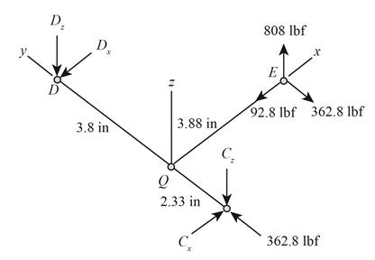
The free body diagram of the shaft.
The reactions at
(a)
Answer to Problem 74P
The free body-diagram of the shaft is as follows.
The reaction at
Explanation of Solution
The figure below shows the arrangement of shafts.
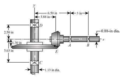
Figure (1)
The free body diagram of the arrangement of shafts is as follows.

Figure (2)
Write the expression of moment at
Here, the reaction at
Write the expression of moment at
Here, the reaction at
Write the expression of moment at
Here, the reaction at
Write the expression of moment at
Write the expression of net force at
Here, the reaction at
Conclusion:
Substitute
Thus, the reaction at
Substitute
Thus, the reaction at
Substitute
Thus, the reaction at
Substitute
Thus, the reaction at
Substitute
Thus, the reaction at
(b)
The shear force and bending moment diagrams.
(b)
Answer to Problem 74P
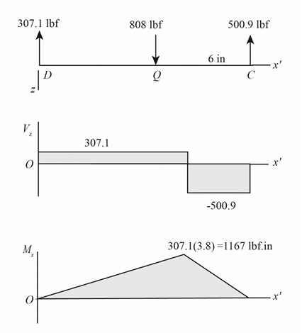
The figure below shows the shear force and bending moment diagram in

The figure below shows the shear force and bending moment diagram in
Explanation of Solution
It is clear from the free body diagram of the shaft
The calculations for shear force diagram in
Write the expression of Shear force at
Here, the shear at
Write the expression of Shear force at
Here, the shear force at
Write the expression of Shear force at
Here, the shear force at
The calculations for bending moment diagram in
We known that, the bending moment at the supports of the simply supported beam is zero.
Write the bending moment at
Here, the bending moment at
Write the expression of bending moment at
Here, the bending moment at
Write the expression of bending moment at
Here, the bending moment at
The calculations for shear force diagram in
Write the expression of Shear force at
Here, the shear at
Write the expression of Shear force at
Here, the shear force at
Write the expression of Shear force at
Here, the shear force at
We known that, the bending moment at the supports of the simply supported beam is zero.
Write the bending moment at
Here, the bending moment at
Write the expression of bending moment at
Here, the bending moment at
Conclusion:
Substitute
Substitute
Substitute
Substitute
Substitute
The figure below shows the shear force and bending moment diagram in
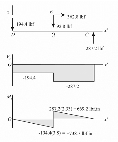
Figure (3)
Substitute
Substitute
Substitute
Substitute
The figure below shows the shear force and bending moment diagram in

Figure (4)
(c)
The torsional shear stress for critical stress element.
The bending stress for critical stress element.
The axial stress for critical stress element.
(c)
Answer to Problem 74P
The torsional shear stress for critical stress element is
The bending stress for critical stress element is
The axial stress for critical stress element is
Explanation of Solution
It is clear from the bending moment diagram that the critical stress element is located at just right of
Write the expression of maximum torque acting on the shaft
Here, the maximum torque acting on the shaft
Write the expression of maximum bending moment acting on the shaft
Here, the maximum bending moment acting on the shaft
Write the expression of torsional shear stress for critical stress element.
Here, the torsional shear stress for critical stress element is
Write the expression of bending stress for critical stress element.
Here, the bending stress for critical stress element is
Write the expression of axial stress for critical stress element.
Here, the axial stress for critical stress element is
Conclusion:
Substitute
Substitute
Substitute
Thus, the torsional shear stress for critical stress element is
Substitute
Thus, the bending stress for critical stress element is
Substitute
Thus, the axial stress for critical stress element is
(d)
The principal stresses for critical stress element.
The maximum shear stress for critical stress element.
(d)
Answer to Problem 74P
The principal stresses for critical stress element are
The maximum shear stress for critical stress element is
Explanation of Solution
Write the expression of maximum bending stress on the critical stress element.
Here, the maximum bending stress on the critical stress element is
Write the expression of principal stresses on the critical stress element.
Here, the principal stresses on the critical stress element are
Write the expression of maximum shear stress on the critical stress element.
Here, the maximum shear stress on the critical stress element is
Conclusion:
Substitute
Substitute
Thus, the principal stresses for critical stress element are
Substitute
Thus, the maximum shear stress for critical stress element is
Want to see more full solutions like this?
Chapter 3 Solutions
Shigley's Mechanical Engineering Design (McGraw-Hill Series in Mechanical Engineering)


- A block hangs from the end of bar AB that is 5.80 meters long and connected to the wall in the xz plane. The bar is supported at end A by a ball joint such that it carries only a compressive force along its axis. The bar is supported in equilibrium at end B by cables BD and BC that connect to the xz plane at points C and D respectively with coordinates given in the figure. The z components of the moments exerted on the bar by these two cables sum to 0. The tension in cable BD is measured to be 210 Newtons. Input answers of zero as 0.00 to avoid an invalid answer due to significant figures. Determine the equivalent force and couple system acting at A that models only the forces exerted by both cables BD → and BC on the bar at B. Enter your results for Feq and Meg in Cartesian Components. Z D (c, 0, d) C (a, 0, b). X A f m B y cc 040 BY NC SA 2016 Eric Davishahl Values for dimensions on the figure are given in the following table. Note the figure may not be to scale. Variable Value a…arrow_forwardA bent tube is attached to a wall with brackets as shown. A force of F = 785 lb is applied to the end of the tube with direction indicated by the dimensions in the figure. a.) Determine the moment about point D due to the force F Enter your answer in Cartesian components with units of ft- lbs. b.) Determine the moment about a line (i.e. axis) running from D to C due to the force F. Enter your answer in Cartesian components with units of ft-lbs. 2013 Michael Swanbom x BY NC SA g Z h A с FK kaz Values for dimensions on the figure are given in the table below. Note the figure may not be to scale. Be sure to align your cartesian unit vectors with the coordinate axes shown in the figure. Variable Value α 4.84 in b 13.2 in с 12.5 in d 30.8 in h 18.7 in 22.0 in →> a. MD=( i+ k) ft- lb →> b. MDC = î + k) ft- lbarrow_forwardF1 3 4 5 P F2 F2 Ꮎ e b 200 3 4 5 F1 The electric pole is subject to the forces shown. Force F1 245 N and force F2 = 310 N with an angle 0 = 20.2°. Determine the moment about point P of all forces. Take counterclockwise moments to be positive. = Values for dimensions on the figure are given in the following table. Note the figure may not be to scale. Variable Value a 2.50 m b 11.3 m с 13.0 m The moment about point P is m. N- If the moment about point P sums up to be zero. Determine the distance c while all other values remained the same. m.arrow_forward
- F y b C 10 Z Determine the moment about O due to the force F shown, the magnitude of the force F = 76.0 lbs. Note: Pay attention to the axis. Values for dimensions on the figure are given in the following table. Note the figure may not be to scale. Variable Value a 1.90 ft b 2.80 ft с 2.60 ft d 2.30 ft Mo = lb + k) ft-arrow_forwardThe shelf bracket is subjected to the force F = 372 Newtons at an angle = 21.4°. Compute the moment (in N-m) that this force exerts about each of the two attachment points (screw locations in the figure). Take counterclockwise moments to be positive. a duk F -0 2013 cc Michael Swanbom BY NC O SA Values for dimensions on the figure are given in the following table. Note the figure may not be to scale. Variable Value a 43.0 cm b 32.3 cm с 2.58 cm The moment about the upper attachment point is N-m. The moment about the lower attachment point is N-m.arrow_forwardA man skis down a slope. His initial elevation was 150 m and his velocity at the bottom of the slope is 17 m/s. What percentage of his initial potential energy was consumed due to friction and air resistance? Use the accounting equation in your calculations.arrow_forward
- In direct calorimetry, a person is placed in a large, water-insulated chamber. The chamber is kept at a constant temperature. While in the chamber, the subject is asked to perform a number of normal activities, such as eating, sleeping, and exercising. The rate of heat released from the subject’s body can be measured by the rate of heat gain by the water bath. Would direct calorimetry be a practical way to measure metabolic rate? Why or why not?A person is placed inside a calorimetric chamber for 24 hours. During this time, the 660-gallon water bath heats up by 3.2°F. What is the subject’s metabolic rate during this period? Report your answer in kcal/day. Assume that there is no heat loss from the water to the surroundings.arrow_forwardUpon reentry into the Earth’s atmosphere, the bottom of a space shuttle heats up to dangerous levels as the craft slows for landing. If the velocity of the shuttle is 28,500 km/hr at the beginning of reentry and 370 km/hr just prior to landing, how much energy is lost as heat? The shuttle has a mass of 90,000 kg. Assume that the change in potential energy is negligible compared to the change in kinetic energy.arrow_forwardof the basket of the balloon at point A, and their other ends are staked to the ground. The hook is located in the geometric center of the basket. The balloon and the air inside it have a combined mass of 3000 kg. You want to determine the resultant of the tension forces in the four cables acting on the hook at point A. It is known that the magnitudes of the tension in the cables are as follows: TAB = 207 N; TAC = 355 N; TAD = 250 N; and TAE = 486 N. B E 2.5 m C E 5.5 m D 2.5 m 3.5 m 1.5 m Using the information provided in the problem, express the force on the hook at point A by cable AC in rectangular component form. The force on the hook at point A by cable AC in rectangular component form is given below. T AC N) i+ N) + N) Rarrow_forward
- Water in the glass tube is at a temperature of 40°C. Plot the height of the water as a function of the tube's inner diameter D for 0.5mm≤D≤3mm. Use increments of 0.5mm. Take sigma=69.6mN/m, and theta=0° for the contact angle.arrow_forwardDetermine the distance h that the column of mercury in the tube will be depressed when the tube is inserted into the mercury at a room temperature of 68 F. Plot this relationship of h (vertical axis) versus D for 0.5 in≤D≤0.150in. Give values for increments of ΔD=0.025in. Discuss this resultarrow_forwardWater is at a temperature of 30 C. Plot the height h of the water as a function of the gap w between the two glass plates for 0.4 mm ≤ w ≤ 2.4 mm. Use increments of 0.4mm. Take sigma=0.0718 N/m.arrow_forward
 Mechanics of Materials (MindTap Course List)Mechanical EngineeringISBN:9781337093347Author:Barry J. Goodno, James M. GerePublisher:Cengage Learning