
Concept explainers
A countershaft carrying two V-belt pulleys is shown in the figure. Pulley A receives power from a motor through a belt with the belt tensions shown. The power is transmitted through the shaft and delivered to the belt on pulley B. Assume the belt tension on the loose side at B is 15 percent of the tension on the Light side.
(a) Determine the tensions in the belt on pulley B, assuming the shaft is running at a constant speed.
(b) Find the magnitudes of the bearing reaction forces, assuming the bearings act as simple supports.
(c) Draw shear-force and bending-moment diagrams for the shaft. If needed, make one set for the horizontal plane and another set for the vertical plane.
(d) At the point of maximum bending moment, determine the bending stress and the torsional shear stress.
(e) At the point of maximum bending moment, determine the principal stresses and the maximum shear stress.
Problem 3–71*
Dimensions in millimeters.
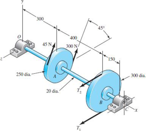
(a)
The tensions in the belt on pulley
Answer to Problem 71P
The tension in the belt pulley
Explanation of Solution
Write the relationship between tension on the loose side with respect to tension on the tight side.
Here, the tension on the tight side is
Write the equation to balance the tension on the counter shaft.
Substitute
Here, the tension on the tight side of pulley
Conclusion:
Substitute
Substitute
Thus, the tension in the belt pulley
(b)
The magnitude of the bearing reaction forces.
Answer to Problem 71P
The magnitude of bearing reaction force at
Explanation of Solution
Write the expression for magnitude of bearing reaction force at
Here, the tension on tight side of pulley
Write the expression for magnitude of bearing reaction force at
Write the expression for magnitude of bearing reaction force at
Here, the magnitude of bearing force at
Write the expression for magnitude of bearing force at
Here, the magnitude of bearing reaction force at
Calculate the bearing reaction force at
Here, the bearing reaction force at
Calculate the bearing reaction force at
Here, the bearing reaction force at
Conclusion:
Substitute
Substitute
Substitute
Substitute
Substitute
Substitute
Thus, the magnitude of bearing reaction force at
(c)
The shear force diagram and bending moment diagram for the shaft.
Answer to Problem 71P
The shear force diagram and bending moment diagram for the shaft in
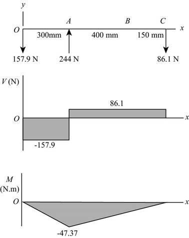
The shear force diagram and bending moment diagram for the shaft in
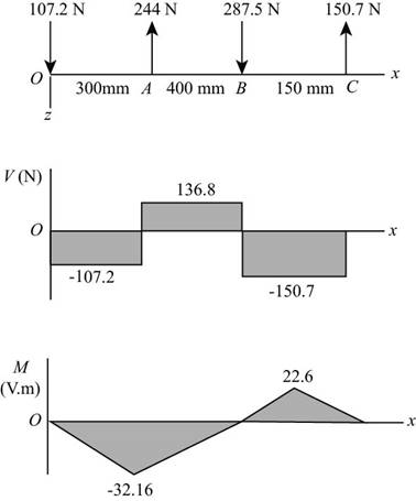
Explanation of Solution
The calculations for shear force and bending moment diagram in
Calculate the shear force at
Here, the shear force at
Calculate the shear force at
Here, the shear force at
Calculate the shear force at
Here, the shear force at
Calculate the moment at
The moment at the supports of the simply supported beam is zero.
Calculate the moment at
Here, the moment at
The calculations for shear force and bending moment diagram in
Calculate the shear force at
Here, the shear force at
Calculate the shear force at
Here, the shear force at
Calculate the shear force at
Calculate the shear force at
Here, the shear force at
Calculate the moment at
The moment at the supports of the simply supported beam is zero.
Calculate the moment at
Here, the moment at
Calculate the moment at
Here, the moment at
Conclusion:
Substitute
Substitute
Substitute
Substitute
Thus, the shear force diagram and bending moment diagram for the shaft in
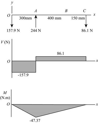
Figure-(1)
Substitute
Substitute
Substitute
Substitute
Substitute
Substitute
Thus, the shear force diagram and bending moment diagram for the shaft in
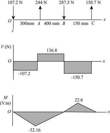
Figure-(2)
(d)
The bending stress at point of maximum bending moment.
The shear stress at point of maximum bending moment.
Answer to Problem 71P
The bending stress at point of maximum bending moment is
The shear stress at point of maximum bending moment is
Explanation of Solution
It is clear from the bending moment diagrams, that the critical location is at
Write the net moment at
Here, the net moment at
Write the torque transmitted by shaft from
Here, the torque transmitted by shaft from
Calculate the bending stress.
Here, the bending stress is
Calculate the shear stress.
Here, the shear stress is
Conclusion:
Substitute
Substitute
Convert the diameter of the shaft from
Substitute
Thus, the bending stress at point of maximum bending moment is
Substitute
Thus, the shear stress at point of maximum bending moment is
(e)
The principal stresses at point of maximum bending moment.
The maximum shear stress at point of maximum bending moment.
Answer to Problem 71P
The principal stresses at point of maximum bending moment are
The maximum shear stress at point of maximum bending moment is
Explanation of Solution
Calculate the maximum principal stress.
Here, the maximum principal stress is
Calculate the minimum principal stress.
Here, the minimum principal stress is
Calculate the maximum shear stress.
Here, maximum shear stress is
Conclusion:
Substitute
Substitute
The principal stresses at point of maximum bending moment are
Substitute
Thus, the maximum shear stress at point of maximum bending moment is
Want to see more full solutions like this?
Chapter 3 Solutions
Shigley's Mechanical Engineering Design (McGraw-Hill Series in Mechanical Engineering)
- The gas tank is made from A-36 steel (σy = 250 MPa) and has an inner diameter of 3.50 m. If the tank is designed to withstand a pressure of 1.2 MPa, determine the required minimum wall thickness to the nearest millimeter using (a) The maximum-shear-stress theory (b) Maximum distortion- energy theory. Apply a factor of safety of 1.5 against yielding.arrow_forwardә レ Figure below shows a link mechanism in which the link OA rotates uniformly in an anticlockwise direction at 10 rad/s. the lengths of the various links are OA=75 mm, OB-150 mm, BC=150 mm, CD-300 mm. Determine for the position shown, the sliding velocity of D. A A B # Space Diagram o NTS (Not-to-Scale) C 10 =--20125 735) 750 x2.01 اهarrow_forward2 レ Tanism in which the link OA mm. O anticlockwise direction at 10 rad/s, the lengths of the various links are OA=75mm, OB=150mm, BC=150mm,CD=300mm. Determine for the position shown, the sliding velocity of D. A A Space Diagram o NT$ (Not-to-Scale) B # C か 750 x2.01 165 79622arrow_forward
- Ashaft fitted with a flywheel rotates at 300 rpm. and drives a machine. The torque required to drive the machine varies in a cyclic manner over a period of 2 revolutions. The torque drops from 20,000 Nm to 10,000 Nm uniformly during 90 degrees and remains constant for the following 180 degrees. It then rises uniformly to 35,000 Nm during the next 225 degrees and after that it drops to 20,000 in a uniform manner for 225 degrees, the cycle being repeated thereafter. Determine the power required to drive the machine and percentage fluctuation in speed, if the driving torque applied to the shaft is constant and the mass of the flywheel is 12 tonnes with radius of gyration of 500 mm. What is the maximum angular acceleration of the flywheel. 35,000 TNM 20,000 10,000 0 90 270 495 Crank angle 8 degrees 720arrow_forwardFigure below shows a link mechanism in which the link OA rotates uniformly in an anticlockwise direction at 10 rad/s. the lengths of the various links are OA=75 mm, OB-150 mm, BC=150 mm, CD-300 mm. Determine for the position shown, the sliding velocity of D. A 45 B Space Diagram o NTS (Not-to-Scale) C Darrow_forwardmotion is as follows; 1- Dwell 45°. Plot the displacement diagram for a cam with flat follower of width 14 mm. The required 2- Rising 60 mm in 90° with Simple Harmonic Motion. 3- Dwell 90°. 4- Falling 60 mm for 90° with Simple Harmonic Motion. 5- Dwell 45°. Then design the cam profile to give the above displacement diagram if the minimum circle diameter of the cam is 50 mm.arrow_forward
- An ideal gas, occupying a volume of 0.02 m3 , has a temperature of 25 0C and is at 1.2 bar. The gas is compressed reversibly and adiabatically to a final pressure of 8 bar. Assuming the gas has an adiabatic index of γ = 1.4, calculate (a) the final temperature, (b) the final volume, (c) the work performed during the compression and (d) the heat transferred.arrow_forwardattached is a past paper question in which we werent given the solution. a solution with clear steps and justification would be massively appreciated thankyou.arrow_forwardin this scenario, when it comes to matrix iterations it states this system is assumed out of phase. why is this?arrow_forward
- Q1. A curved beam of a circular cross section of diameter "d" is fixed at one end and subjected to a concentrated load P at the free end (Fig. 1). Calculate stresses at points A and C. Given: P = 800 N, d = 30 mm, a 25 mm, and b = 15 mm. Fig.1 P b B (10 Marks)arrow_forwardYou are working as an engineer in a bearing systems design company. The flow of lubricant inside a hydrodynamic bearing (p = 0.001 kg m-1 s-1) can be approximated as a parallel, steady, two-dimensional, incompressible flow between two parallel plates. The top plate, representing the moving part of the bearing, travels at a constant speed, U, while the bottom plate remains stationary (Figure Q1). The plates are separated by a distance of 2h = 1 cm and are W = 20 cm wide. Their length is L = 10 cm. By applying the above approximations to the Navier-Stokes equations and assuming that end effects can be neglected, the horizontal velocity profile can be shown to be y = +h I 2h = 1 cm x1 y = -h u(y) 1 dP 2μ dx -y² + Ay + B moving plate stationary plate U 2 I2 L = 10 cm Figure Q1: Flow in a hydrodynamic bearing. The plates extend a width, W = 20 cm, into the page.arrow_forwardQuestion 1 You are working as an engineer in a bearing systems design company. The flow of lubricant inside a hydrodynamic bearing (µ = 0.001 kg m¯¹ s¯¹) can be approximated as a parallel, steady, two-dimensional, incompressible flow between two parallel plates. The top plate, representing the moving part of the bearing, travels at a constant speed, U, while the bottom plate remains stationary (Figure Q1). The plates are separated by a distance of 2h = 1 cm and are W = 20 cm wide. Their length is L = 10 cm. By applying the above approximations to the Navier-Stokes equations and assuming that end effects can be neglected, the horizontal velocity profile can be shown to be 1 dP u(y) = 2μ dx -y² + Ay + B y= +h Ꮖ 2h=1 cm 1 x1 y = −h moving plate stationary plate 2 X2 L = 10 cm Figure Q1: Flow in a hydrodynamic bearing. The plates extend a width, W = 20 cm, into the page. (a) By considering the appropriate boundary conditions, show that the constants take the following forms: U U 1 dP A =…arrow_forward
 Mechanics of Materials (MindTap Course List)Mechanical EngineeringISBN:9781337093347Author:Barry J. Goodno, James M. GerePublisher:Cengage Learning
