
Concept explainers
Videos
Repeat Prob. 3–15 for:
(a) σx = 28 MPa, σy = 7 MPa, τxy = 6 MPa cw
(b) σx = 9 MPa, σy = –6 MPa, τxy = 3 MPa cw
(c) σx = –4 MPa, σy = 12 MPa, τxy = 7 MPa ccw
(d) σx = 6 MPa, σy = –5 MPa, τxy = 8 MPa ccw
(a)
The principle normal stress.
The shear stress.
The angle from
Answer to Problem 16P
The principle normal stress
The shear stress is
The angle from
Explanation of Solution
Write the coordinates of the points through which the Mohr’s circle pass.
Here, the stress along x face is
Draw the
Write the formula for the center point.
Here, the center point is
Write the expression for the angle between the line joining points A and B with
Here, the angle made by the diameter with positive x-axis in the counterclockwise direction is
Write the expression of the radius of circle.
Write the expression maximum in plane normal stress.
Here, the maximum in plane normal stress are
Write the expression of maximum in plane shear stress.
Here, the maximum shear stress is
Write the expression for the angle of maximum shear plane.
Here, the angle is
Conclusion:
Substitute the value
Draw the Mohr’s circle diagram.
The Figure (1) shows the Mohr’s circle diagram.
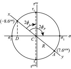
Figure (1)
Substitute the value
Substitute the value
Thus, the angle from
Substitute the value
Substitute the value
Thus, the principle normal stress
Substitute the value
Thus, the principle normal stress
Substitute the value
Thus, the shear stress is
Substitute the value
The Figure (2) shows the maximum in plane normal stress distribution about the plane.
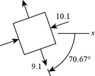
Figure (2)
The Figure (3) shows stress distribution at maximum shear stress plane.
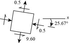
Figure (3)
(b)
The principle normal stress.
The shear stress.
The angle from
Answer to Problem 16P
The principle normal stress
The shear stress is
The angle from
Explanation of Solution
Write the coordinates of the points through which the Mohr’s circle pass.
Draw the
Write the formula for the center point.
Write the expression for the angle between the line joining points A and B with
Write the expression of the radius of circle.
Write the expression maximum in plane normal stress.
Write the expression of maximum in plane shear stress.
Write the expression for the angle of maximum shear plane.
Write the expression for the angle between the line joining points A and B with
Conclusion:
Substitute
Substitute
Draw the Mohr’s circle diagram.
The Figure (4) shows the Mohr’s circle diagram.
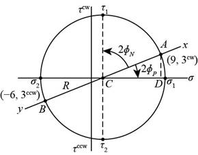
Figure (4)
Substitute the value
Substitute the value
Thus, the angle from
Substitute the value
Substitute
Thus, the principle normal stress
Substitute
Thus, the principle normal stress
Substitute the value
Thus, the shear stress is
Substitute the value
The Figure (5) shows the maximum in plane normal stress distribution about the plane.
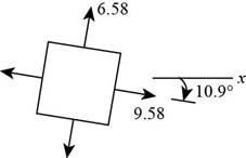
Figure (5)
The Figure (6) shows stress distribution at maximum shear stress plane.
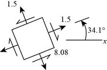
Figure (6)
Thus, the principle normal stress
(c)
The principle normal stress.
The shear stress.
The angle from
Answer to Problem 16P
The principle normal stress
The shear stress is
The angle from
Explanation of Solution
Write the coordinates of the points through which the Mohr’s circle pass.
Draw the
Write the formula for the center point.
Write the expression for the angle between the line joining points A and B with
Write the expression of the radius of circle.
Write the expression maximum in plane normal stress.
Write the expression of maximum in plane shear stress.
Write the expression for the angle of maximum shear plane.
Conclusion:
Substitute the value
Substitute
Draw the Mohr’s circle diagram.
Figure (7) shows the Mohr’s circle diagram.
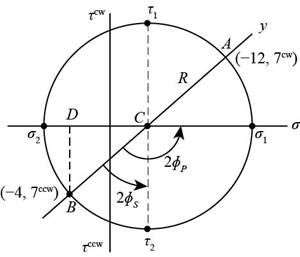
Figure (7)
Substitute the value
Substitute the value
Substitute the value
Substitute the value
Substitute the value
Substitute the value
Substitute the value
The Figure (8) shows the maximum in plane normal stress distribution about the plane.
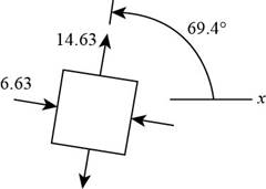
Figure (8)
The Figure (9) shows stress distribution at maximum shear stress plane.
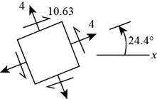
Figure (9)
Thus, the he principle normal stress
(d)
The principle normal stress.
The shear stress.
The angle from
Answer to Problem 16P
The principle normal stress
The shear stress is
The angle from
Explanation of Solution
Write the coordinates of the points through which the Mohr’s circle pass.
Draw the
Write the formula for the center point.
Write the expression for the angle between the line joining points A and B with
Write the expression of the radius of circle.
Write the expression maximum in plane normal stress.
Write the expression of maximum in plane shear stress.
Write the expression for the angle of maximum shear plane.
Write the expression for the angle between the line joining points A and B with
Conclusion:
Substitute
Substitute
Draw the Mohr’s circle diagram.
The Figure (10) shows the Mohr’s circle diagram.
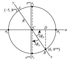
Figure (10)
Substitute the value
Substitute the value
Substitute the value
Substitute the value
Substitute the value
Substitute the value
Substitute the value
The Figure (11) shows the maximum in plane normal stress distribution about the plane.
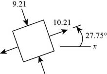
Figure (11)
The Figure (12) shows stress distribution at maximum shear stress plane.
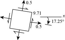
Figure (12)
Thus, the principle normal stress
Want to see more full solutions like this?
Chapter 3 Solutions
Shigley's Mechanical Engineering Design (McGraw-Hill Series in Mechanical Engineering)


- (Read image)arrow_forward(Read Image)arrow_forwardM16x2 grade 8.8 bolts No. 25 C1- Q.2. The figure is a cross section of a grade 25 cast-iron pressure vessel. A total of N, M16x2.0 grade 8.8 bolts are to be used to resist a separating force of 160 kN. (a) Determine ks, km, and C. (b) Find the number of bolts required for a load factor of 2 where the bolts may be reused when the joint 19 mm is taken apart. (c) with the number of bolts obtained in (b), determine the realized load factor for overload, the yielding factor of safety, and the separation factor of safety. 19 mmarrow_forward
- Problem4. The thin uniform disk of mass m = 1-kg and radius R = 0.1m spins about the bent shaft OG with the angular speed w2 = 20 rad/s. At the same time, the shaft rotates about the z-axis with the angular speed 001 = 10 rad/s. The angle between the bent portion of the shaft and the z-axis is ẞ = 35°. The mass of the shaft is negligible compared to the mass of the disk. a. Find the angular momentum of the disk with respect to point G, based on the axis orientation as shown. Include an MVD in your solution. b. Find the angular momentum of the disk with respect to point O, based on the axis orientation as shown. (Note: O is NOT the center of fixed-point rotation.) c. Find the kinetic energy of the assembly. z R R 002 2R x Answer: H = -0.046ĵ-0.040 kg-m²/sec Ho=-0.146-0.015 kg-m²/sec T 0.518 N-m =arrow_forwardProblem 3. The assembly shown consists of a solid sphere of mass m and the uniform slender rod of the same mass, both of which are welded to the shaft. The assembly is rotating with angular velocity w at a particular moment. Find the angular momentum with respect to point O, in terms of the axes shown. Answer: Ñ。 = ½mc²wcosßsinßĵ + (}{mr²w + 2mb²w + ½ mc²wcos²ß) k 3 m r b 2 C لا marrow_forwardOnly question 2arrow_forward
- Only question 1arrow_forwardOnly question 3arrow_forwardI have Euler parameters that describe the orientation of N relative to Q, e = -0.7071*n3, e4 = 0.7071. I have Euler parameters that describe the orientation of U relative to N, e = -1/sqrt(3)*n1, e4 = sqrt(2/3). After using euler parameter rule of successive rotations, I get euler parameters that describe the orientation of U relative to Q, e = -0.4082*n1 - 0.4082*n2 - 0.5774*n3. I need euler parameters that describe the orientation of U relative to Q in vector basis of q instead of n. How do I get that?arrow_forward
- Describe at least 4 processes in engineering where control charts are (or should be) appliedarrow_forwardDescribe at least two (2) processes where control charts are (or should be) applied.arrow_forwardProblem 3: A cube-shaped spacecraft is in a circular Earth orbit. Let N (n,) be inertial and the spacecraft is denoted S (ŝ₁). The spacecraft is described such that ¯½º = J ŝ₁ŝ₁ + J ŝ₂§₂ + J §¸Ŝ3 Location of the spacecraft in the orbit is determined by the orbit-fixed unit vectors ê, that are oriented by the angle (Qt), where is a constant angular rate. 52 €3 3> 2t 55 Λ Из At the instant when Qt = 90°, the spacecraft S is oriented relative to the orbit such that 8₁ = 0° Space-three 1-2-3 angles 0₂ = 60° and ES = $₂ rad/s 0₁ = 135° (a) At this instant, determine the direction cosine matrix that describes the orientation of the spacecraft with respect to the inertial frame N.arrow_forward
 Mechanics of Materials (MindTap Course List)Mechanical EngineeringISBN:9781337093347Author:Barry J. Goodno, James M. GerePublisher:Cengage Learning