
Power System Analysis and Design (MindTap Course List)
6th Edition
ISBN: 9781305632134
Author: J. Duncan Glover, Thomas Overbye, Mulukutla S. Sarma
Publisher: Cengage Learning
expand_more
expand_more
format_list_bulleted
Concept explainers
Videos
Textbook Question
Chapter 3, Problem 3.33P
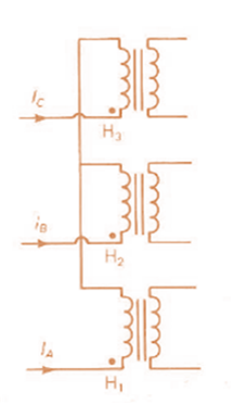
Consider the three single-phase two-winding transformers shown in Figure 3.37. The high-voltage windings are connected in Y. (a) For the low-voltage side, connect the windings in
Expert Solution & Answer
Want to see the full answer?
Check out a sample textbook solution
Students have asked these similar questions
I need help checking if its correct
-E1 + VR1 + VR4 – E2 + VR3 = 0 -------> Loop 1 (a)
R1(I1) + R4(I1 – I2) + R3(I1) = E1 + E2 ------> Loop 1 (b)
R1(I1) + R4(I1) - R4(I2) + R3(I1) = E1 + E2 ------> Loop 1 (c)
(R1 + R3 + R4) (I1) - R4(I2) = E1 + E2 ------> Loop 1 (d)
Now that we have loop 1 equation will procced on finding the equation of I2 current loop. However, a reminder that because we are going in a clockwise direction, it goes against the direction of the current. As such we will get an equation for the matrix that will be:
E2 – VR4 – VR2 + E3 = 0 ------> Loop 2 (a)
-R4(I2 – I1) -R2(I2) = -E2 – E3 ------> Loop 2 (b)
-R4(I2) + R4(I1) - R2(I2) = -E2 – E3 -----> Loop 2 (c)
R4(I1) – (R4 + R2)(I2) = -E2 – E3 -----> Loop 2 (d)
These two equations will be implemented to the matrix formula I = inv(A) * b
R11 R12
(R1 + R3 + R4)
-R4
-R4
R4 + R2
10.2 For each of the following groups of sources, determineif the three sources constitute a balanced source, and if it is,determine if it has a positive or negative phase sequence.(a) va(t) = 169.7cos(377t +15◦) Vvb(t) = 169.7cos(377t −105◦) Vvc(t) = 169.7sin(377t −135◦) V(b) va(t) = 311cos(wt −12◦) Vvb(t) = 311cos(wt +108◦) Vvc(t) = 311cos(wt +228◦) V(c) V1 = 140 −140◦ VV2 = 114 −20◦ VV3 = 124 100◦ V
Apply single-phase equivalency to determine the linecurrents in the Y-D network shown in Fig. P10.13. The loadimpedances are Zab = Zbc = Zca = (25+ j5) W
Chapter 3 Solutions
Power System Analysis and Design (MindTap Course List)
Ch. 3 - The Ohms law for the magnetic circuit states that...Ch. 3 - For an ideal transformer, the efficiency is (a) 0...Ch. 3 - For an ideal 2-winding transformer, the...Ch. 3 - An ideal transformer has no real or reactive power...Ch. 3 - For an ideal 2-winding transformer, an impedance...Ch. 3 - Consider Figure 3.4. For an ideal phase-shifting...Ch. 3 - Consider Figure 3.5. Match the following, those on...Ch. 3 - The units of admittance, conductance, and...Ch. 3 - Match the following: (i) Hysteresis loss (a) Can...Ch. 3 - For large power transformers rated more than 500...
Ch. 3 - For a short-circuit test on a 2-winding...Ch. 3 - The per-unit quantity is always dimensionless. (a)...Ch. 3 - Consider the adopted per-unit system for the...Ch. 3 - The ideal transformer windings are eliminated from...Ch. 3 - To convert a per-unit impedance from old to new...Ch. 3 - In developing per-unit circuits of systems such as...Ch. 3 - Prob. 3.17MCQCh. 3 - Prob. 3.18MCQCh. 3 - With the American Standard notation, in either a...Ch. 3 - Prob. 3.20MCQCh. 3 - In order to avoid difficulties with third-harmonic...Ch. 3 - Does an open connection permit balanced...Ch. 3 - Does an open- operation, the kVA rating compared...Ch. 3 - It is stated that (i) balanced three-phase...Ch. 3 - In developing per-unit equivalent circuits for...Ch. 3 - In per-unit equivalent circuits of practical...Ch. 3 - Prob. 3.27MCQCh. 3 - Prob. 3.28MCQCh. 3 - For developing per-unit equivalent circuits of...Ch. 3 - Prob. 3.30MCQCh. 3 - Prob. 3.31MCQCh. 3 - Prob. 3.32MCQCh. 3 - The direct electrical connection of the windings...Ch. 3 - Consider Figure 3.25 of the text for a transformer...Ch. 3 - (a) An ideal single-phase two-winding transformer...Ch. 3 - An ideal transformer with N1=1000andN2=250 is...Ch. 3 - Consider an ideal transformer with...Ch. 3 - A single-phase 100-kVA,2400/240-volt,60-Hz...Ch. 3 - Prob. 3.5PCh. 3 - Prob. 3.6PCh. 3 - Consider a source of voltage v(t)=102sin(2t)V,...Ch. 3 - Prob. 3.8PCh. 3 - Prob. 3.9PCh. 3 - A single-phase step-down transformer is rated...Ch. 3 - For the transformer in Problem 3.10. The...Ch. 3 - Prob. 3.12PCh. 3 - A single-phase 50-kVA,2400/240-volt,60-Hz...Ch. 3 - A single-phase 50-kVA,2400/240-volt,60-Hz...Ch. 3 - Rework Problem 3.14 if the transformer is...Ch. 3 - A single-phase, 50-kVA,2400/240-V,60-Hz...Ch. 3 - The transformer of Problem 3.16 is supplying a...Ch. 3 - Using the transformer ratings as base quantities,...Ch. 3 - Using the transformer ratings as base quantities....Ch. 3 - Using base values of 20 kVA and 115 volts in zone...Ch. 3 - Prob. 3.21PCh. 3 - A balanced Y-connected voltage source with...Ch. 3 - Figure 3.32 shows the oneline diagram of a...Ch. 3 - For Problem 3.18, the motor operates at full load,...Ch. 3 - Consider a single-phase electric system shown in...Ch. 3 - A bank of three single-phase transformers, each...Ch. 3 - A three-phase transformer is rated...Ch. 3 - For the system shown in Figure 3.34. draw an...Ch. 3 - Consider three ideal single-phase transformers...Ch. 3 - Reconsider Problem 3.29. If Va,VbandVc are a...Ch. 3 - Prob. 3.31PCh. 3 - Determine the positive- and negative-sequence...Ch. 3 - Consider the three single-phase two-winding...Ch. 3 - Three single-phase, two-winding transformers, each...Ch. 3 - Consider a bank of this single-phase two-winding...Ch. 3 - Three single-phase two-winding transformers, each...Ch. 3 - Three single-phase two-winding transformers, each...Ch. 3 - Consider a three-phase generator rated...Ch. 3 - The leakage reactance of a three-phase,...Ch. 3 - Prob. 3.40PCh. 3 - Consider the single-line diagram of the power...Ch. 3 - For the power system in Problem 3.41, the...Ch. 3 - Three single-phase transformers, each rated...Ch. 3 - A 130-MVA,13.2-kV three-phase generator, which has...Ch. 3 - Figure 3.39 shows a oneline diagram of a system in...Ch. 3 - The motors M1andM2 of Problem 3.45 have inputs of...Ch. 3 - Consider the oneline diagram shown in Figure 3.40....Ch. 3 - With the same transformer banks as in Problem...Ch. 3 - Consider the single-Line diagram of a power system...Ch. 3 - A single-phase three-winding transformer has the...Ch. 3 - The ratings of a three-phase three-winding...Ch. 3 - Prob. 3.52PCh. 3 - The ratings of a three-phase, three-winding...Ch. 3 - An infinite bus, which is a constant voltage...Ch. 3 - A single-phase l0-kVA,2300/230-volt,60-Hz...Ch. 3 - Three single-phase two-winding transformers, each...Ch. 3 - A two-winding single-phase transformer rated...Ch. 3 - A single-phase two-winding transformer rated...Ch. 3 - Prob. 3.59PCh. 3 - PowerWorid Simulator case Problem 3_60 duplicates...Ch. 3 - Rework Example 3.12 for a+10 tap, providing a 10...Ch. 3 - A 23/230-kV step-up transformer feeds a...Ch. 3 - The per-unit equivalent circuit of two...Ch. 3 - Reconsider Problem 3.64 with the change that now...Ch. 3 - What are the advantages of correctly specifying a...Ch. 3 - Why is it important to reduce the moisture within...Ch. 3 - What should be the focus of transformer preventive...
Knowledge Booster


Learn more about
Need a deep-dive on the concept behind this application? Look no further. Learn more about this topic, electrical-engineering and related others by exploring similar questions and additional content below.Similar questions
- 10.8 In the network of Fig. P10.8, Za = Zb = Zc = (25+ j5) W.Determine the line currents.arrow_forwardUsing D flip-flops, design a synchronous counter. The counter counts in the sequence 1,3,5,7, 1,7,5,3,1,3,5,7,.... when its enable input x is equal to 1; otherwise, the counter count 0. Present state Next state x=0 Next state x=1 Output SO 52 S1 1 S1 54 53 3 52 53 S2 56 51 0 $5 5 54 S4 53 0 55 58 57 7 56 56 55 0 57 S10 59 1 58 58 S7 0 59 S12 S11 7 $10 $10 59 0 $11 $14 $13 5 $12 S12 $11 0 513 $15 SO 3 S14 $14 S13 0 $15 515 SO 0 Explain how to get the table step by step with drawing the state diagram and finding the Karnaugh map.arrow_forwardFor the oscillator resonance circuit shown in Fig. (5), derive the oscillation frequency Feedback and open-loop gains. L₁ 5 mH (a) ell +10 V R₁ ww R3 S C2 HH 1 με 1000 pF 100 pF R₂ 1 με RA H (b) +9 V R4 CA 470 pF C₁ R3 HH 1 με R₁ ww L₁ 000 1.5 mH R₂ ww Hi 1 μF L2 m 10 mHarrow_forward
- Expert handwritten solution onlyarrow_forwardB. For the oscillator circuit shown in frequency, feedback and open-loop gains. +10 V name the circuit, derive and find the oscillation P.Av +9 V -000 4₁ 5 mH w R₁ C₂ HH 1 με w 100 pF R₂ T R CA www. 470 pF w ww www 1000 pF HH 1μF C₁ HH 1μF Ra ww HI 4₁ 000 1.5 mH H 4 AF 000 10 mHarrow_forwardI want to check if the current that I have from using the mesh analysis is correct? I1 = 0.214mA I2 = -0.429mAarrow_forward
- I want to find the current by using mesh analysis pleasearrow_forwardI want to find the current by using mesh analysis pleasearrow_forwardR₁ W +10 V R3 +9 V C₂ R₁ CA C₁ 470 pF HH 1000 pF HH 1 με C4 1 μF 1 uF C₁ R₂ R4 100 pF Find Open-loop Jain L₁ 5 mH (a) Av=S,B={" H R₁₂ ✓ ww (b) R₁ L₁ 000 1.5 mH R₂ H 1 uF 12 10 mHarrow_forward
- A) Calculate the efficiency of the test transformer at the resistive loads (X-25%, 50%, 75%, 100%, 125% full load). B) From part (A) draw the plot (efficiency Vs power output) of the transformer. C) Discuss the plot of part (B).arrow_forwarda- Determine fH; and Ho b- Find fg and fr. c- Sketch the frequency response for the high-frequency region using a Bode plot and determine the cutoff frequency. Ans: 277.89 KHz; 2.73 MHz; 895.56 KHz; 107.47 MHz. 14V Cw=5pF Cwo-8pF Coc-12 pF 5.6kQ Ch. 40. pF C-8pF 68kQ 0.47µF Vo 0.82 kQ V₁ B=120 0.47µF www 3.3kQ 10kQ 1.2kQ =20µF Narrow_forwardUsing D flip-flops, design a synchronous counter. The counter counts in the sequence 1,3,5,7, 1,7,5,3,1,3,5,7,.... when its enable input x is equal to 1; otherwise, the counter. This counter is for individual settings only need the state diagram and need the state table to use 16 states from So to S15.arrow_forward
arrow_back_ios
SEE MORE QUESTIONS
arrow_forward_ios
Recommended textbooks for you
 Power System Analysis and Design (MindTap Course ...Electrical EngineeringISBN:9781305632134Author:J. Duncan Glover, Thomas Overbye, Mulukutla S. SarmaPublisher:Cengage Learning
Power System Analysis and Design (MindTap Course ...
Electrical Engineering
ISBN:9781305632134
Author:J. Duncan Glover, Thomas Overbye, Mulukutla S. Sarma
Publisher:Cengage Learning
TRANSFORMERS - What They Are, How They Work, How Electricians Size Them; Author: Electrician U;https://www.youtube.com/watch?v=tXPy4OE7ApE;License: Standard Youtube License