
Concept explainers
Videos
Expression for vehicle’s speed as a function of time (
Answer to Problem 3.29P
The vehicle’s speed as a function of time,
Explanation of Solution
Given:
Weight of a rear wheel = 500 lb.
Weight of front wheel = 800 lb.
Weight of the body = 9000 lb.
Radius of rear wheel = 4ft.
Radius of front wheel = 2ft.
Concept used:
The object in question can translate in two dimensions and can rotate only about an axis that is perpendicular to the plane.
Object in question is a rigid body that moves in a plane passing through its mass center.
The motion of this object is defined by its translational motion in the plane and its rotational motion about an axis perpendicular to the plane. Two force equations describe the translational motion, and a moment equation is needed to describe the rotational motion.
The two force equations of the translational motion:
Using Newton’s laws for plane motion,
Where,
For an objects’ planar motion which rotates only about an axis perpendicular to the plane, the equation of motion can be written down using Newton’s Second Law.
Equation of Motion:
Where
Here the rotation is about the mass center, G, and the angular acceleration is taken as
Where
Derivation of Equation of motion:
Taking the body and the wheels as separate systems with axle,
Free body diagram of the body of the road roller:
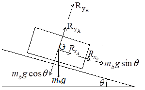
Force equations of the translational motion of body:
In the x -direction,
The acceleration,
In the y -direction,
The acceleration,
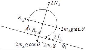
Free body diagram of the front wheel:
Sum of force in x -direction:
Sum of force in y -direction:
The acceleration,
Moments equation:
Where,
Assuming the wheels are rolling without slipping,
Modelling the wheels as a cylinder of radius
Substituting
Substitute
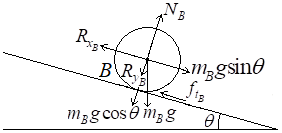
Free body diagram of the rear wheels:
Sum of force in x -direction:
Sum of force in y -direction:
The acceleration,
Moments equation:
Where,
Assuming the wheels are rolling without slipping,
Modelling the wheels as a cylinder of radius
Substituting
Substitute
Substitute
Substitute the given values to equation
Conclusion:
The vehicle’s speed as a function of time,
Want to see more full solutions like this?
Chapter 3 Solutions
System Dynamics


- Draw the shear and bending-moment diagrams for the beam and loading shown, and determine the maximum normal stress due to bending. 4.8 kips/ft 32 kips B C D E I Hinge 8 ft. 2 ft 5 ft 5 ft W12 x 40arrow_forward2nd Law of Thermodynamics A rigid, insulated tank that is initially evacuated is connected through a valve to the supply line that carrieshelium at 300 kPa and 140◦C. Now the valve is opened, and helium is allowed to flow into the tank until thepressure reaches 300 kPa, at which point the valve is closed. Determine the flow work of the helium in thesupply line and the final temperature of the helium in the tank.arrow_forwardDraw the shear and bending-moment diagrams for the beam and loading shown, and determine the maximum normal stress due to bending. 5 kips 10 kips B I W14 x 22 -5 ft -8 ft 5 ft-arrow_forward
- 2nd Law of Thermodynamics Liquid water at 200 kPa and 25◦C is heated in a chamber by mixing it with superheated steam at 200 kPaand 250◦C. cold water enters the chamber at a rate of 2 kg/s. If the mixture leaves the mixing chamber at50◦C, determine the mass flow rate of the superheated steam required.arrow_forwardThe 2nd Law of Thermodynamics Refrigerant-134a enters the compressor of a refrigeration system as saturated vapor at 0.16 MPa, and leavesas superheated vapor at 0.9 MPa and 70◦C at a rate of 0.08 kg/s. Determine the rates of energy transfers bymass into and out of the compressor. Assume the kinetic and potential energies are negligible.arrow_forward2nd Law of Thermodynamics Water enters the tubes of a cold plate at 65◦C with an average velocity of 50 ft/min and leaves at 110◦F. Thediameter of the tubes is 0.2 in. Assuming 20 percent of the heat generated is dissipated from the componentsto the surroundings by convection and radiation, and the remaining 80 percent is removed by the coolingwater, determine the amount of heat generated by the electronic devices mounted on the cold plate.arrow_forward
- The 2nd Law of Thermodynamics Refrigerant-134a enters a diffuser steadily as saturated vapor 500 kPa with a velocity of 170 m/s, and it leavesat 600 kPa and 50◦C. the refrigerant is gaining heat at a rate of 2.5 kJ/s as it passes through the diffuser. Ifthe exit area is 75 percent greater than the inlet area, determine (a) the exit velocity (b) the mass flow rate of the refrigerant.arrow_forward2nd Law of Thermodynamics Refrigerant-134a is throttled from the saturated liquid state at 850 kPa to a pressure of 200 kPa. Determinethe temperature drop during this process and the final specific volume of the refrigerant.arrow_forward2nd Law of Thermodynamics An adiabatic gas turbine expands air at 1350 kPa and 525◦C to 125 kPa and 130◦C. Air enters the tur-bine through a 0.15-m2 opening with an average velocity of 50 m/s, and exhausts through a 1-m2 opening.Determine (a) the mass flow rate of air through the turbine (b) the power produced by the turbine.arrow_forward
- The 2nd Law of Thermodynamics Air is compressed from 12 psia and 77.3◦F to a pressure of 145 psia while being cooled at a rate of 15Btu/lbm by circulating water through the compressor casing. The volume flow rate of the air at the inletconditions is 6000 ft3/min, and the power input to the compressor is 800 hp. Determine (a) the mass flow rate of the air (b) the temperature at the compressor exitarrow_forwardI need solution by handarrow_forwardDraw the shear and bending-moment diagrams for the beam and loading shown, and determine the maximum normal stress due to bending. 4.8 kips/ft 32 kips B C D E I Hinge 8 ft. 2 ft 5 ft 5 ft W12 x 40arrow_forward
 Elements Of ElectromagneticsMechanical EngineeringISBN:9780190698614Author:Sadiku, Matthew N. O.Publisher:Oxford University Press
 Mechanics of Materials (10th Edition)Mechanical EngineeringISBN:9780134319650Author:Russell C. HibbelerPublisher:PEARSON
 Thermodynamics: An Engineering ApproachMechanical EngineeringISBN:9781259822674Author:Yunus A. Cengel Dr., Michael A. BolesPublisher:McGraw-Hill Education
 Control Systems EngineeringMechanical EngineeringISBN:9781118170519Author:Norman S. NisePublisher:WILEY
 Mechanics of Materials (MindTap Course List)Mechanical EngineeringISBN:9781337093347Author:Barry J. Goodno, James M. GerePublisher:Cengage Learning
 Engineering Mechanics: StaticsMechanical EngineeringISBN:9781118807330Author:James L. Meriam, L. G. Kraige, J. N. BoltonPublisher:WILEY