
System Dynamics
3rd Edition
ISBN: 9780073398068
Author: III William J. Palm
Publisher: MCG
expand_more
expand_more
format_list_bulleted
Concept explainers
Videos
Textbook Question
Chapter 3, Problem 3.11P
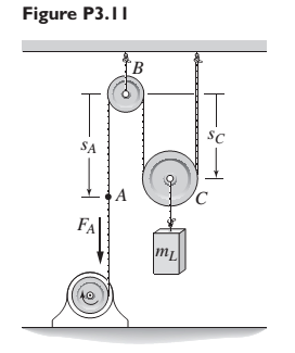
The motor in Figure P3.11 lifts the mass
Expert Solution & Answer
Want to see the full answer?
Check out a sample textbook solution
Students have asked these similar questions
Stress, ksi
160
72
150-
140
80
70
༄ ྃ ༈ ཎྜ རྦ ༅ ཎྜ ྣཧྨ ➢
130
120
110
100
90
2.0
2.8
3.6
4.4
5
Wire diameter, mm
6.0
6.8
2
7.6
8.4
Compression and extension springs.
ASTM A227 Class II
Light service
Average service
0.020
0.060
0.100
0.140
0.180
0.220
0.260
0.300
0.340
0.380
0.420
0.460
0.500
Wire diameter, in
Torsional stress due to initial tension, ksi
10
४
20
Preferred
range
100
Stress, MPa
9.2
10.0
10.8
11.6
12.4
1100
1035
965
895
825
760
Severe service
690
620
550
50
150
3456789 10 11 12 13 14 15 16
Spring index, C = DJD
FIGURE 18-21 Recommended torsional shear stress in an extension spring due to initial tension (Data from Associated
Spring, Barnes Group, Inc.)
50
200
485
Stress, MPa
Bolted Joint Design
Bolted Frames
Total Force due to door weight: P =
240
lb
Number of Bolts: N =
Distance to Bolt C/L: a =
4
N/A
Bolt Material -
Allowable shear stress of bolt material: T₂ =
x Distance from Bolt centroid to bolt: x =
y Distance from Bolt centroid to bolt: y =
Degrees per Radian-
Results
y-Load on each bolt: F, =
Moment resisted by bolt pattern: M =
Radial distance from Bolt centroid to bolt: r =
Sum squares of all radial distances: Σr²
Force on each bolt to resist moment: F, -
Angle for force composition: e=
X-Force on each bolt to resist moment: F-
y-Force on each bolt to resist moment: Fly
Total y-Force on each bolt: Fy =
Resultant force on bolt 1: R₁ =
Required shear stress area for a bolt: A₂ =
ASTM Grade
A307 Steel
10,000
0
psi
from Table 20-1
3.0
57.296
in
degrees
lb per bolt
lb-in
Formula
FS-P/N
M-Px XB
r = (x² + y²)0.5
in²
Σ
4r²
Mr
F₁ =
Στ
lb
degrees
lb
lb
lb
Minimum Bolt Diameter: Din =
Rounded up Bolt Diameter: D =
55
P.
1.5 in
2 in (3x)
1 in
This bracket…
University of Babylon
Collage of Engineering/
Al-Musayab
Department of Automobiles
Final Examination/ Stage: 3rd
Notes:
Answer 4 questions only
2023-2202
Subject: Theory of vehicles
Date: 2023\06\10-Saturday
Time: Three Hours
Course 2nd Attempt 1st
Q1: A Hooke's coupling connects two shafts whose axes are inclined at 30°. The
of the driven shaft? Find the maximum value of retardation or acceleration and
driving shaft rotates uniformly at 600 rpm. What are the extreme angular velocities
state the angle where both will occur.
(12.5 Marks)
Q2: Four masses, A, B, C, and D), revolve at equal radii and are equally spaced
along a shaft. The mass B is 7 kg, and the radius of C and D make angles of 90°
and 240°, respectively, with the radius of B. Find the magnitude of the masses A,
C, and D and the angular position of A so that the system may be completely
balanced.
(12.5 Marks)
Q3: A cam has straight worked faces that are tangential to a base circle of diameter
90 mm. The follower is a roller…
Chapter 3 Solutions
System Dynamics
Ch. 3 - Prob. 3.1PCh. 3 - A baseball is thrown horizontally from the...Ch. 3 - For the mass shown in Figure 3.1.3b. m=10 kg, =25...Ch. 3 - A particle of mass m=19 kg slides down a...Ch. 3 - A particle of mass m slides down a frictionless...Ch. 3 - A radar tracks the flight of a projectile (see...Ch. 3 - Table 3.2.1 gives the inertia IO for a point mass...Ch. 3 - A motor supplies a moment M to the pulley of...Ch. 3 - Figure P3.9 shows an inverted pendulum. Obtain the...Ch. 3 - The two masses shown in Figure P3.10 are released...
Ch. 3 - The motor in Figure P3.11 lifts the mass mL by...Ch. 3 - Instead of using the system shown in Figure 3.2.6a...Ch. 3 - Consider the cart shown in Figure P3.13. Suppose...Ch. 3 - Consider the cart shown in Figure P3.13. Suppose...Ch. 3 - Consider the spur gears shown in Figure P3.15,...Ch. 3 - Consider the spur gears shown in Figure P3.15,...Ch. 3 - Derive the expression for the equivalent inertia...Ch. 3 - Prob. 3.18PCh. 3 - The geared system shown in Figure P3.19 represents...Ch. 3 - Prob. 3.20PCh. 3 - Prob. 3.21PCh. 3 - Prob. 3.22PCh. 3 - For the geared system shown in Figure P3.23,...Ch. 3 - For the geared system discussed in Problem 3.23,...Ch. 3 - The geared system shown in Figure P3.25 is similar...Ch. 3 - Consider the rack-and-pinion gear shown in Figure...Ch. 3 - The lead screw (also called a power screw or a...Ch. 3 - Prob. 3.29PCh. 3 - Derive the equation of motion of the block of mass...Ch. 3 - Assume the cylinder in Figure P3.31 rolls without...Ch. 3 - Prob. 3.33PCh. 3 - Prob. 3.34PCh. 3 - A slender rod 1.4 m long and of mass 20 kg is...Ch. 3 - Prob. 3.36PCh. 3 - Prob. 3.37PCh. 3 - The pendulum shown in Figure P3.38 consists of a...Ch. 3 - Prob. 3.39PCh. 3 - A single link of a robot arm is shown in Figure...Ch. 3 - 3.41 It is required to determine the maximum...Ch. 3 - Figure P3.42 illustrates a pendulum with a base...Ch. 3 - Figure P3.43 illustrates a pendulum with a base...Ch. 3 - 3.44 The overhead trolley shown in Figure P3.44 is...Ch. 3 - Prob. 3.45PCh. 3 - The “sky crane” shown on the text cover was a...
Knowledge Booster


Learn more about
Need a deep-dive on the concept behind this application? Look no further. Learn more about this topic, mechanical-engineering and related others by exploring similar questions and additional content below.Similar questions
- Problem 18-26 Added Extension Springs Spring Material ASTM A227 Modulus of Elasticity of the Material in Shear: G 1.150E+07 psi Average Service Max Operating Load: F₁ = 100 lb Max Length between attachment points: L₁ = 60.00 in 20.00 lb 26.00 1.400 Min Operating Load: F₁ = Min Length between attachment points: L₁ = Maximum Outside Diameter = in in Results Note: you select a wire diameter from the "US steel wire gage" column in table 18-2 Formula k = AF/AL k = (F0-F1)/(Lo - L₁) Spring Rate: k = lb/in Assumed Trial Outside Diameter: OD = Assumed Trial Mean: D ma Assumed Design Stress in Spring: Tda in 1.070 in 102,000 psi Assumed Wahl Factor: K = 1.2 Calculated Wire Diameter: Dwa Actual Wire Diameter: Dw Actual outer diameter: OD = Actual inner diameter: ID= Spring Index: C = See Figure 18-8 Dw= [8KF Dm πTd 1/3 in 5' 5' 5' 5' This corresponds to US Steel 9 wire gage ID = Dm - Dw C = Dm/Dw 4C - 1 0.615 K = + 4C - с Wahl Factor: K = 8KFDm 8KFC T = TD πD Stress in Spring at F = Fo: To psi…arrow_forwardCHAIN DRIVE DESIGN Initial Input Data: Application: Garage Door Opener Drive type: AC Motor Driven machine Chain and Sprocket to pull the door up Degrees per Radian: 57.2958 degrees Sprocket Diameter: D = 1.690 in Number of strands: Chain number: 1 40 Service factor: 1.3 Table 7-10 No. of teeth Computed Data: Actual Motor Power Input: 0.000 hp Sprocket Speed (for sprocket attached to gear shaft) Design power: 0.00 rpm 0 hp 11 12 0.06 0.15 0.29 0.56 0.99 1.09 1.61 2.64 TABLE 7-7 Horsepower Ratings-Single Strand Roller Chain No. 40 0.500 inch pitch 10 25 50 100 180 200 300 500 700 900 1000 1: 0.06 0.14 0.27 0.52 0.91 1.00 1.48 2.42 3.34 4.25 4.70 ! 3.64 4.64 5.13 13 0.07 0.16 0.31 0.61 1.07 1.19 1.75 2.86 3.95 5.02 5.56 Design Decisions-Chain Type and Teeth Numbers: 14 Chain number: Use Table 7-7 Chain pitch: p = in 15 Number of Teeth: N = Per Table 7-7 16 0.08 0.20 0.39 0.75 1.32 1.46 2.15 3.52 0.07 0.17 0.34 0.66 1.15 1.28 1.88 3.08 0.08 0.19 0.36 0.70 1.24 1.37 2.02 3.30 4.55 5.80…arrow_forwardInput Data: Torque needed to overcome rolling friction in rollers, slides and other moving parts, except for Motor and Worm Gear the worm gear T₁ = Length of travel of door: Time for door to open or close: LD = 50 lb-in. 90 in t= 12.5 seconds Pitch diameter for chain sprocket: DPC 1.690 in Weight of Door: P = No. of worm threads: Nw = Worm Pitch diameter: Dw Diametral pitch: Pd Normal pressure angle: Degrees per Radian: Number of gear teeth: Calculated Data: Linear velocity of door and chain (in/sec): Linear velocity of door and chain (ft/min): Output Speed of Gear and Sprocket: Upward Force due to Weight of Door: Фо = = NG= 240 lb 2 1.250 in 12 14.5 degrees 57.2958 degrees 28 Vα= in/sec VC= ft/min NG = rpm FD lb Net Upward Force on Door: Fou lb Torque on gear ignoring rolling friction: TG = lb-in. Formula = FDU FD-2 x Fo (note: Fo is the Max Operating load of the extension springs). This is also the initial tension in the chain. TG = FDU X DPC/2 This is the also the torque on the…arrow_forward
- Q5/A: A car with a track of 1.5 m and a wheelbase of 2.9 m has a steering gear mechanism of the Ackermann type. The distance between the front stub axle pivots is 1.3 m. The length of each track arm is 150 mm, and the length of the track rod is 1.2 m. Find the angle turned through by the outer wheel if the angle turned through by the inner wheel is 30°. (6 Marks) Q5/B: Write True on the correct sentences and False on the wrong sentences listed below:- 1- In automobiles, the power is transmitted from the gearbox to the differential through bevel gears. 2- The minimum radius circle drawn to the cam profile is called the base circle. 3- The Proell governor, compared to the Porter governor, has less lift at the same speed. 4- The balancing of rotating and reciprocating parts of an engine is necessary when it runs at a slow speed. (6.5 Marks) ***Best of Luck *** جامعة بابل UNIVERSITY OF BABYLON Examiner: Mohanad R. Hameed Head of Department: Dr. Dhyai H. Jawadarrow_forwardUniversity of Babylon Collage of Engineering/ Al-Musayab Department of Automobiles Mid Examination/ Stage: 3rd Subject: Theory of Vehicles Date: 14 \ 4 \2025 Time: 1.5 Hours 2025-2024 Q1: The arms of a Porter governor are 250 mm long. The upper arms are pivoted on the axis of revolution, but the lower arms are attached to a sleeve at a distance of 50 mm from the axis of rotation. The weight on the sleeve is 600 N and the weight of each ball is 80 N. Determine the equilibrium speed when the radius of rotation of the balls is 150 mm. If the friction is equivalent to a load of 25 N at the sleeve, determine the range of speed for this position. Q2: In a loaded Proell governor shown in Figure below each ball weighs 3 kg and the central sleeve weighs 25 kg. The arms are of 200 mm length and pivoted about axis displaced from the central axis of rotation by 38.5 mm, y=238 mm, x=303.5 mm, CE 85 mm, MD 142.5 mm. Determine the equilibrium speed. Fe mg E M 2 Q3: In a spring loaded Hartnell type…arrow_forwardusing the theorem of three moments, find all the reactions and supports, I need the calculations onlyarrow_forward
- Q.5: (10 Marks) Select the correct answer (choose 10 only) 1. The forward whirling speed is ......... the static structure tilting speed. (a) Less than (b) Higher than (c) equal to 2. The divergence between the forward and backward whirling speeds increases as: (a) The rotating speed increase (b) the polar moment of inertia increases (c) Both (a) and (b) (d) do not change 3. Increasing the system natural frequency can be done by: (a) add masses (b) adding braces and supports (c) increase damping 4. The amplitude of vibration due to external force can be reduced by: (a) Increasing damping (b) Decreasing damping (c) Increasing mass 5. Tuned absorbers are used to: (a) Shift the natural frequency (b) increase damping (c) Increase stiffness 6. Accelerometers sensors contains: г (a) Piezoelectric materials (b) Magnet and coil (c) coil only 7. Increasing the stiffness of the system causes: (a) Less transmitted force (b) more transmitted force (c) Transmitted force does not change 8. The…arrow_forwardQ.1: (15 Marks) Find the first three natural frequencies and mode shapes of the axial and torsional vibration for a steel shaft free at both ends, having a length of 3 m. Find the subsequent axil motion if the shaft is subjected to the following initial conditions, given that E = 210 GPa, G=80 GPa, p = 7800 kg/m³: f(x)=0 v(x) = {1 2.8arrow_forwardQ.4: (15 Marks) A uniform rotor of mass 500 kg and diametral moment of inertia of 20 kg.m², is supported by identical short bearings of stiffness 1 MN/m in the horizontal and vertical directions. If the distance between the bearings is 0.6 m: (a) What is the corresponding polar moment of inertia if the backward whirling speed is 80% of the static structure tilting natural frequency? (b) Determine the forward whirling speed. 45.27arrow_forwardUniversity of Babylon Collage of Engineering/ Al-Musayab Department of Automobiles Mid Examination/ Stage: 3rd Subject: Theory of Vehicles Date: 14 \ 4 \2025 Time: 1.5 Hours 2025-2024 Q1: The arms of a Porter governor are 250 mm long. The upper arms are pivoted on the axis of revolution, but the lower arms are attached to a sleeve at a distance of 50 mm from the axis of rotation. The weight on the sleeve is 600 N and the weight of each ball is 80 N. Determine the equilibrium speed when the radius of rotation of the balls is 150 mm. If the friction is equivalent to a load of 25 N at the sleeve, determine the range of speed for this position. Q2: In a loaded Proell governor shown in Figure below each ball weighs 3 kg and the central sleeve weighs 25 kg. The arms are of 200 mm length and pivoted about axis displaced from the central axis of rotation by 38.5 mm, y=238 mm, x=303.5 mm, CE 85 mm, MD 142.5 mm. Determine the equilibrium speed. Fe mg E M 2 Q3: In a spring loaded Hartnell type…arrow_forwardQ.2: (15 Marks) = 1400 For the following system, determine the first natural frequency using Dunkerley's equation, Given that the disk has moment of inertia J = 2 kg.m², the shaft has G = 20 GPa, p kg/m³, polar moment of cross-sectional area of the shaft Ip = 8×10⁸ m². 500 mm 220 mm k=200 N/m FOF m=1 kg 14.14 56.56. W слarrow_forwardQ.2: (15 Marks) = 1400 For the following system, determine the first natural frequency using Dunkerley's equation, Given that the disk has moment of inertia J = 2 kg.m², the shaft has G = 20 GPa, p kg/m³, polar moment of cross-sectional area of the shaft Ip = 8×10⁸ m². 500 mm 220 mm k=200 N/m FOF m=1 kg 14.14 56.56. W слarrow_forwardarrow_back_iosSEE MORE QUESTIONSarrow_forward_ios
Recommended textbooks for you
 Elements Of ElectromagneticsMechanical EngineeringISBN:9780190698614Author:Sadiku, Matthew N. O.Publisher:Oxford University Press
 Mechanics of Materials (10th Edition)Mechanical EngineeringISBN:9780134319650Author:Russell C. HibbelerPublisher:PEARSON
 Thermodynamics: An Engineering ApproachMechanical EngineeringISBN:9781259822674Author:Yunus A. Cengel Dr., Michael A. BolesPublisher:McGraw-Hill Education
 Control Systems EngineeringMechanical EngineeringISBN:9781118170519Author:Norman S. NisePublisher:WILEY
 Mechanics of Materials (MindTap Course List)Mechanical EngineeringISBN:9781337093347Author:Barry J. Goodno, James M. GerePublisher:Cengage Learning
 Engineering Mechanics: StaticsMechanical EngineeringISBN:9781118807330Author:James L. Meriam, L. G. Kraige, J. N. BoltonPublisher:WILEY
Elements Of Electromagnetics
Mechanical Engineering
ISBN:9780190698614
Author:Sadiku, Matthew N. O.
Publisher:Oxford University Press
Mechanics of Materials (10th Edition)
Mechanical Engineering
ISBN:9780134319650
Author:Russell C. Hibbeler
Publisher:PEARSON
Thermodynamics: An Engineering Approach
Mechanical Engineering
ISBN:9781259822674
Author:Yunus A. Cengel Dr., Michael A. Boles
Publisher:McGraw-Hill Education
Control Systems Engineering
Mechanical Engineering
ISBN:9781118170519
Author:Norman S. Nise
Publisher:WILEY
Mechanics of Materials (MindTap Course List)
Mechanical Engineering
ISBN:9781337093347
Author:Barry J. Goodno, James M. Gere
Publisher:Cengage Learning
Engineering Mechanics: Statics
Mechanical Engineering
ISBN:9781118807330
Author:James L. Meriam, L. G. Kraige, J. N. Bolton
Publisher:WILEY
Dynamics - Lesson 1: Introduction and Constant Acceleration Equations; Author: Jeff Hanson;https://www.youtube.com/watch?v=7aMiZ3b0Ieg;License: Standard YouTube License, CC-BY