College Physics: A Strategic Approach (3rd Edition)
3rd Edition
ISBN: 9780321879721
Author: Randall D. Knight (Professor Emeritus), Brian Jones, Stuart Field
Publisher: PEARSON
expand_more
expand_more
format_list_bulleted
Videos
Textbook Question
Chapter 23, Problem 31P
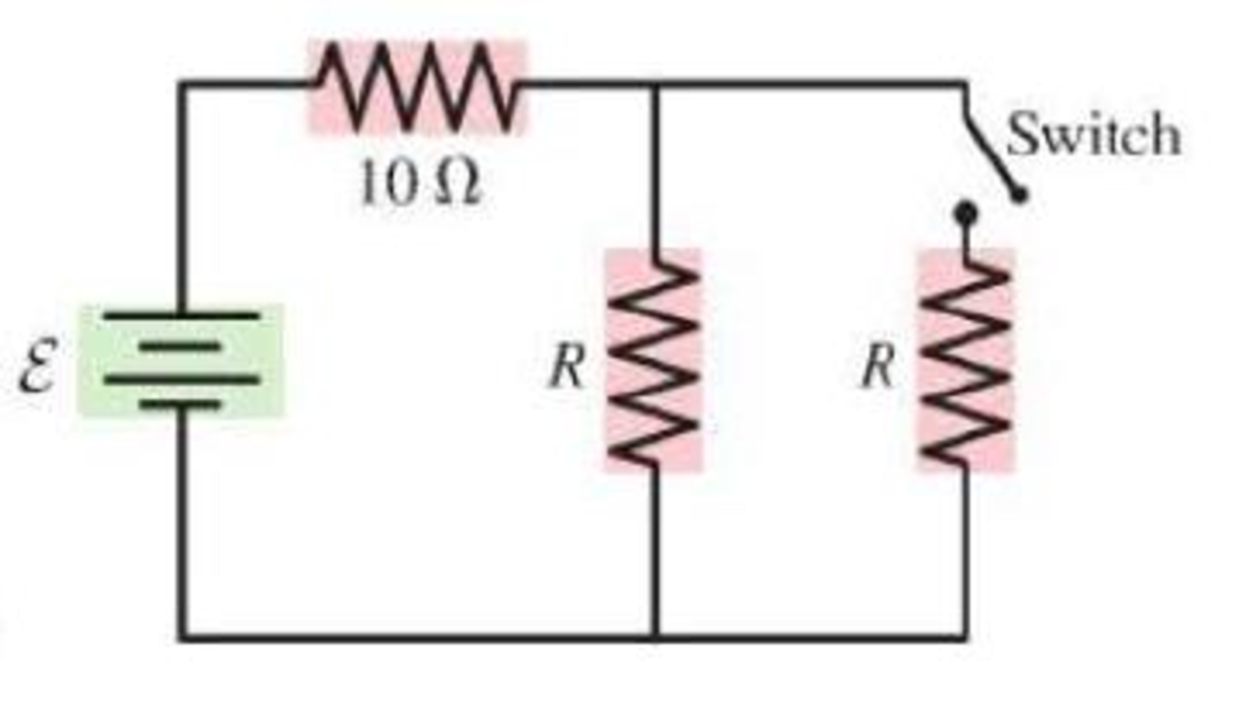
The two unknown resistors in Figure P23.31 have the same resistance R. When the switch is closed, the current through the battery increases by 50%. What is R?
Figure P23.31
Expert Solution & Answer
Want to see the full answer?
Check out a sample textbook solution
Students have asked these similar questions
Help with all of this question please.
The current through the 30 Ω resistor shown is measured to be 0.25 A. What is the emf ε of the battery?
Two batteries supply current to the circuit in the figure. The figure shows the potential difference across two of the resistors and the value of the third resistor. What current is supplied by the batteries?
Chapter 23 Solutions
College Physics: A Strategic Approach (3rd Edition)
Ch. 23 - The tip of a flashlight bulb is touching the top...Ch. 23 - A flashlight bulb is connected to a battery and is...Ch. 23 - Current Iin flows into three resistors connected...Ch. 23 - The circuit in Figure Q23.4 has two resistors,...Ch. 23 - The circuit in Figure Q23.5 has a battery and two...Ch. 23 - In the circuit shown in Figure Q23.6, bulbs A and...Ch. 23 - Figure Q23.7 shows two circuits. The two batteries...Ch. 23 - Figure Q23.8 shows two circuits. The two batteries...Ch. 23 - a. In Figure Q23.9, what fraction of current I...Ch. 23 - Two of the three resistors in Figure Q23.10 are...
Ch. 23 - Two of the three resistors in Figure Q23.11 are...Ch. 23 - Rank in order, from largest to smallest, the...Ch. 23 - The three bulbs in Figure Q23.13 are identical....Ch. 23 - The four bulbs in Figure Q23.14 are identical....Ch. 23 - Figure Q23.15 shows five identical bulbs connected...Ch. 23 - a. The three bulbs in Figure Q23.16 are identical....Ch. 23 - Initially, bulbs A and B in Figure Q23.17 are both...Ch. 23 - a. Consider the points a and b in Figure Q23.18....Ch. 23 - When the switch in Figure Q23.19 is closed, a....Ch. 23 - A voltmeter is (incorrectly) inserted into a...Ch. 23 - An ammeter is (incorrectly) inserted into a...Ch. 23 - Rank in order, from largest to smallest, the...Ch. 23 - Figure Q23.23 shows a circuit consisting of a...Ch. 23 - Figure Q23.24 shows the volt age as a function of...Ch. 23 - A charged capacitor could be connected to two...Ch. 23 - A flashing light is controlled by the charging and...Ch. 23 - A device to make an electrical measurement of skin...Ch. 23 - Consider the model of nerve conduction in...Ch. 23 - Adding a myelin sheath to an axon results in...Ch. 23 - What is the current in the circuit of Figure...Ch. 23 - Which resistor in Figure Q23.30 dissipates the...Ch. 23 - Normally, household lightbulbs are connected in...Ch. 23 - A metal wire of resistance R is cut into two...Ch. 23 - What is the value of resistor R in Figure Q23.34?...Ch. 23 - Two capacitors are connected in series. They are...Ch. 23 - If a cells membrane thickness doubles but the cell...Ch. 23 - If a cells diameter is reduced by 50% without...Ch. 23 - Draw a circuit diagram tor the circuit of Figure...Ch. 23 - Draw a circuit diagram for the circuit of Figure...Ch. 23 - Draw a circuit diagram for the circuit of Figure...Ch. 23 - In Figure P23.4, what is the current in the wire...Ch. 23 - The lightbulb in the circuit diagram of Figure...Ch. 23 - a. What are the magnitude and direction of the...Ch. 23 - a. What are the magnitude and direction of the...Ch. 23 - a. What is the potential difference across each...Ch. 23 - The current in a circuit with only one battery is...Ch. 23 - What is the equivalent resistance of each group of...Ch. 23 - What is the equivalent resistance of each group of...Ch. 23 - Prob. 12PCh. 23 - Prob. 13PCh. 23 - You have a collection of 1.0 k resistors. How can...Ch. 23 - You have a collection of six 1.0 k resistors. What...Ch. 23 - You have six 1.0 k resistors. How can you connect...Ch. 23 - What is the equivalent resistance between points a...Ch. 23 - What is the equivalent resistance between points a...Ch. 23 - The currents in two resistors in a circuit are...Ch. 23 - Two batteries supply current to the circuit in...Ch. 23 - Part of a circuit is shown in Figure P23.21. a....Ch. 23 - What is the value of resistor R in Figure P23.22?...Ch. 23 - What are the resistances R and the emf of the...Ch. 23 - The ammeter in Figure P23.24 reads 3.0 A. Find I1,...Ch. 23 - Find the current through and the potential...Ch. 23 - Find the current through and the potential...Ch. 23 - For the circuit shown in Figure P23.27, find the...Ch. 23 - Consider the potential differences between pairs...Ch. 23 - For the circuit shown in Figure P23.29, find the...Ch. 23 - A photoresistor, whose resistance decreases with...Ch. 23 - The two unknown resistors in Figure P23.31 have...Ch. 23 - A 6.0 F capacitor, a 10 F capacitor, and a 16 F...Ch. 23 - A 6.0 F capacitor, a 10 F capacitor, and a 16 F...Ch. 23 - You need a capacitance of 50 F, but you dont...Ch. 23 - You need a capacitance of 50 F, but you dont...Ch. 23 - What is the equivalent capacitance of the three...Ch. 23 - What is the equivalent capacitance of the three...Ch. 23 - For the circuit of Figure P23.38, a. What is the...Ch. 23 - For the circuit of Figure P23.39. a. What is the...Ch. 23 - What is the time constant for the discharge of the...Ch. 23 - What is the time constant for the discharge of the...Ch. 23 - After how many time constants has the voltage...Ch. 23 - A 10F capacitor initially charged to 20C is...Ch. 23 - A capacitor charging circuit consists of a...Ch. 23 - The switch in Figure P23.45 has been in position a...Ch. 23 - A 9.0-nm-thick cell membrane undergoes an action...Ch. 23 - A cell membrane has a resistance and a capacitance...Ch. 23 - Changing the thickness of the myelin sheath...Ch. 23 - A particular myelinated axon has nodes spaced 0.80...Ch. 23 - To measure signal propagation in a nerve in the...Ch. 23 - A myelinated axon conducts nerve impulses at a...Ch. 23 - How much power is dissipated by each resistor in...Ch. 23 - Two 75 W (120 V) lightbulbs are wired in series,...Ch. 23 - The corroded contacts in a lightbulb socket have...Ch. 23 - A real battery is not just an emf. We can If model...Ch. 23 - For the real battery shown in Figure P23.55,...Ch. 23 - Batteries are recharged by connecting them to a...Ch. 23 - When two resistors are connected in parallel...Ch. 23 - The 10 resistor in Figure P23.59 is dissipating 40...Ch. 23 - At this instant the current in the circuit of...Ch. 23 - What is the equivalent resistance between points a...Ch. 23 - What is the current through the battery in Figure...Ch. 23 - What is the ratio P parallel/P series of the total...Ch. 23 - You have a device that needs a voltage reference...Ch. 23 - There is a current of 0.25 A in the circuit of...Ch. 23 - A circuit youre building needs an ammeter that...Ch. 23 - A circuit youre building needs a voltmeter that...Ch. 23 - For the circuit shown in Figure P23.68, find the...Ch. 23 - You have three 12 F capacitors. Draw diagrams...Ch. 23 - Initially, the switch in Figure P23.70 is in...Ch. 23 - The capacitor in an RC circuit with a time...Ch. 23 - The capacitor in Figure P23.72 is initially...Ch. 23 - What value resistor will discharge a 1.0 F...Ch. 23 - The charging circuit for the flash system of a...Ch. 23 - A capacitor is discharged through a 100 resistor....Ch. 23 - A 50 /F capacitor that had been charged to 30 V is...Ch. 23 - The switch in Figure P23.77 has been closed for a...Ch. 23 - Intermittent windshield wipers use a variable...Ch. 23 - In Example 23.14 we estimated the capacitance of...Ch. 23 - The giant axon of a squid is 0.5 mm in diameter,...Ch. 23 - A cell has a 7.0-nm-thick membrane with a total...Ch. 23 - The Defibrillator A defibrillator is designed to...Ch. 23 - The Defibrillator A defibrillator is designed to...Ch. 23 - The Defibrillator A defibrillator is designed to...Ch. 23 - A defibrillator is designed to pass a large...Ch. 23 - The voltage produced by a single nerve or muscle...Ch. 23 - The voltage produced by a single nerve or muscle...Ch. 23 - The voltage produced by a single nerve or muscle...Ch. 23 - The voltage produced by a single nerve or muscle...
Additional Science Textbook Solutions
Find more solutions based on key concepts
Starting from rest, a hollow ball rolls down a ramp inclined at angle to the horizontal. Find an expression fo...
Essential University Physics: Volume 1 (3rd Edition)
Explain all answers clearly, with complete sentences and proper essay structure if needed. An asterisk (*) desi...
The Cosmic Perspective Fundamentals (2nd Edition)
Express the unit vectors in terms of (that is, derive Eq. 1.64). Check your answers several ways Also work o...
Introduction to Electrodynamics
Imagine you are comparing the ability of electric hot plates of different sizes and temperatures to fully cook ...
Lecture- Tutorials for Introductory Astronomy
The pV-diagram of the Carnot cycle.
Sears And Zemansky's University Physics With Modern Physics
42. Rank the following in order of increasing duration: One minute on the surface of (a) Earth. (b) Mercury. (c...
Conceptual Physical Science (6th Edition)
Knowledge Booster


Learn more about
Need a deep-dive on the concept behind this application? Look no further. Learn more about this topic, physics and related others by exploring similar questions and additional content below.Similar questions
- In Figure P29.81, N real batteries, each with an emf and internal resistance r, are connected in a closed ring. A resistor R can be connected across any two points of this ring, causing there to be n real batteries in one branch and N n resistors in the other branch. Find an expression for the current through the resistor R in this case.arrow_forwardWhat is the equivalent resistance between points a and b of the six resistors shown in Figure P29.70? FIGURE P29.70arrow_forwardThe circuit shown in Figure P28.78 is set up in the laboratory to measure an unknown capacitance C in series with a resistance R = 10.0 M powered by a battery whose emf is 6.19 V. The data given in the table are the measured voltages across the capacitor as a function of lime, where t = 0 represents the instant at which the switch is thrown to position b. (a) Construct a graph of In (/v) versus I and perform a linear least-squares fit to the data, (b) From the slope of your graph, obtain a value for the time constant of the circuit and a value for the capacitance. v(V) t(s) In (/v) 6.19 0 5.56 4.87 4.93 11.1 4.34 19.4 3.72 30.8 3.09 46.6 2.47 67.3 1.83 102.2arrow_forward
- A potential difference of 1.00 V is maintained across a 10.0- resistor for a period of 20.0 s. What total charge passes by a point in one of the wires connected to the resistor in this time interval? (a) 200 C (b) 20.0 C (c) 2.00 C (d) 0.005 00 C (e) 0.050 0 Carrow_forwardFigure P18.37 shows a simplified model of a cardiac defibrillator, a device used to patients in ventricular fibrillation. When the switch S is toggled to the left, the capacitor C charges through the resistor R .When the switch is toggled to the right, the capacitor discharges current through the patients torso, modeled as the resistor Rtorso, allowing the hearts normal rhythm to be reestablished. (a) If the capacitor is initially uncharged with C = 8.00 F and = 1250 V, find the value of R required to charge the capacitor to a voltage of 775 V in 1.50 s. (b) If the capacitor is then discharged across the patients torso with, Rtorso = 1250 , calculate the voltage across the capacitor after 5.00 ms. Figure P18.37arrow_forwardThe current in a circuit with only one battery is 2.0 A. Shown is how the potential changes when going around the circuit in the clockwise direction, starting from the lower left corner. Draw the circuit diagram.arrow_forward
- What is the charge Q on the capacitor immediately after the switch is changed? What is the current I through the resistor immediately after the switch is changed?arrow_forward25.54. In the circuit shown in Fig. P25.54, R is a variable resistor whose value ranges from 0 to co, and a and b are the terminals of a battery that has an emf E = 15.0V and an internal resistance of 4.00 2. The ammeter and voltmeter are idealized meters. As R varies over its full range of values, what will be the largest and smallest readings of (a) the voltmeter and (b) the ammeter? (c) Sketch qualita- tive graphs of the readings of both meters as functions of R. Figure P25.54 Rarrow_forwardWhat is the equivalent resistance between points a and b as shown?arrow_forward
- There is a current of 0.25 A in the circuit of Figure P23.69.a. What is the direction of the current? Explain.b. What is the value of the resistance R?c. What is the power dissipated by R?d. Make a graph of potential versus position, starting from V = 0 V in the lower left corner and proceeding clockwise.See Figure P23.9 for an example.arrow_forwardA 10 MΩ resistor is connected in series with a 1.0 μF capacitor and a battery with emf 12.0 V. Before the switch is closed at time t=0,the capacitor is uncharged. What fraction of the final charge Qf is on the capacitor at t=10s?arrow_forwardhelparrow_forward
arrow_back_ios
SEE MORE QUESTIONS
arrow_forward_ios
Recommended textbooks for you
 Physics for Scientists and Engineers: Foundations...PhysicsISBN:9781133939146Author:Katz, Debora M.Publisher:Cengage Learning
 Principles of Physics: A Calculus-Based TextPhysicsISBN:9781133104261Author:Raymond A. Serway, John W. JewettPublisher:Cengage Learning
 Physics for Scientists and Engineers, Technology ...PhysicsISBN:9781305116399Author:Raymond A. Serway, John W. JewettPublisher:Cengage Learning
 College PhysicsPhysicsISBN:9781305952300Author:Raymond A. Serway, Chris VuillePublisher:Cengage Learning
Physics for Scientists and Engineers: Foundations...
Physics
ISBN:9781133939146
Author:Katz, Debora M.
Publisher:Cengage Learning
Principles of Physics: A Calculus-Based Text
Physics
ISBN:9781133104261
Author:Raymond A. Serway, John W. Jewett
Publisher:Cengage Learning
Physics for Scientists and Engineers, Technology ...
Physics
ISBN:9781305116399
Author:Raymond A. Serway, John W. Jewett
Publisher:Cengage Learning
College Physics
Physics
ISBN:9781305952300
Author:Raymond A. Serway, Chris Vuille
Publisher:Cengage Learning
DC Series circuits explained - The basics working principle; Author: The Engineering Mindset;https://www.youtube.com/watch?v=VV6tZ3Aqfuc;License: Standard YouTube License, CC-BY