
Control Systems Engineering
7th Edition
ISBN: 9781118170519
Author: Norman S. Nise
Publisher: WILEY
expand_more
expand_more
format_list_bulleted
Concept explainers
Videos
Textbook Question
Chapter 2, Problem 31P
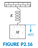
For the unexcited (no external force applied) system of Figure P2.16, do the following:
a. Write the differential equation that describes the system.
b. Assuming initial conditions x(0) = x0and
c. Find x(t) by obtaining the inverse Laplace transform from the result in Part c.
d. What will be the oscillation frequency in Hz for this system?
Expert Solution & Answer
Want to see the full answer?
Check out a sample textbook solution
Students have asked these similar questions
Air enters the 1-m2 inlet of an aircraft engine at 100 kPa and 20°C with a velocity of 184 m/s. Determine the volume flow rate, in m3/s, at the engine’s inlet and the mass flow rate, in kg/s, at the engine’s exit. The gas constant of air is R = 0.287 kPa·m3/kg·K.
The volume flow rate at the engine’s inlet m3/s.
The mass flow rate at the engine’s exit is kg/s.
The ventilating fan of the bathroom of a building has a volume flow rate of 33 L/s and runs continuously. If the density of air inside is 1.20 kg/m3, determine the mass of air vented out in one day.
The mass of air is kg.
A steady-flow compressor is used to compress helium from 15 psia and 70°F at the inlet to 200 psia and 600°F at the outlet. The outlet area and velocity are 0.01 ft2 and 100 ft/s, respectively, and the inlet velocity is 53 ft/s. Determine the mass flow rate and the inlet area. The gas constant of helium is R = 2.6809 psia·ft3/lbm·R.
The mass flow rate is lbm/s.
The inlet area is ft2.
Chapter 2 Solutions
Control Systems Engineering
Ch. 2 - Prob. 1RQCh. 2 - Prob. 2RQCh. 2 - Prob. 3RQCh. 2 - Define the transfer function.Ch. 2 - Prob. 5RQCh. 2 - What do we call the mechanical equations written...Ch. 2 - If we understand the form the mechanical equations...Ch. 2 - Why do transfer functions for mechanical networks...Ch. 2 - What function do gears perform?Ch. 2 - What are the component parts of the mechanical...
Ch. 2 - The motor’s transfer function relates armature...Ch. 2 - Summarize the steps taken to linearize a nonlinear...Ch. 2 - Prob. 1PCh. 2 - Prob. 2PCh. 2 - Prob. 3PCh. 2 - Prob. 4PCh. 2 - Prob. 5PCh. 2 - Prob. 6PCh. 2 - Prob. 7PCh. 2 - A system is described by the following...Ch. 2 - For each of the following transfer functions,...Ch. 2 - Write the differential equation for the system...Ch. 2 - Write the differential equation that is...Ch. 2 - Prob. 12PCh. 2 - Use MATLAB to generate the MATLAB ML transfer...Ch. 2 - Repeat Problem 13 for the MATLAB following...Ch. 2 - Use MATLAB to generate the partial fraction...Ch. 2 - Use MATLAB and the Symbolic Math Symbolic Math...Ch. 2 - Prob. 17PCh. 2 - Prob. 18PCh. 2 - Prob. 19PCh. 2 - Repeat Problem 19 using nodal equations. [Section:...Ch. 2 - Prob. 22PCh. 2 - Prob. 23PCh. 2 - Prob. 24PCh. 2 - Prob. 25PCh. 2 - Prob. 26PCh. 2 - Prob. 27PCh. 2 - Prob. 28PCh. 2 - Prob. 29PCh. 2 - Write, but do not solve, the equations of motion...Ch. 2 - For the unexcited (no external force applied)...Ch. 2 - For each of the rotational mechanical systems...Ch. 2 - For the rotational mechanical system shown in...Ch. 2 - Find the transfer function, 1sTs , for the system...Ch. 2 - For the rotational mechanical system with gears...Ch. 2 - For the rotational system shown in Figure P2.21,...Ch. 2 - Prob. 37PCh. 2 - Find the transfer function, Gs=4s/Ts , for the...Ch. 2 - For the rotational system shown in Figure P2.24,...Ch. 2 - Prob. 40PCh. 2 - Given the rotational system shown in Figure P226,...Ch. 2 - In the system shown in Figure P2.27, the inertia,...Ch. 2 - Prob. 43PCh. 2 - Given the combined translational and rotational...Ch. 2 - Prob. 45PCh. 2 - The motor whose torque-speed characteristics are...Ch. 2 - A dc motor develops 55 N-m of torque at a speed of...Ch. 2 - 48. In this chapter, we derived the transfer...Ch. 2 - Prob. 49PCh. 2 - Find the series and parallel analogs for the...Ch. 2 - Find the series and parallel analogs for the...Ch. 2 - A system’s output, c, is related to the system’s...Ch. 2 - Prob. 53PCh. 2 - Consider the differential equation...Ch. 2 - 55. Many systems are piecewise linear. That is,...Ch. 2 - For the translational mechanical system with a...Ch. 2 - 57. Enzymes are large proteins that biological...Ch. 2 - Prob. 58PCh. 2 - Figure P2.36 shows a crane hoisting a load....Ch. 2 - 60. In 1978, Malthus developed a model for human...Ch. 2 - 61. In order to design an underwater vehicle that...Ch. 2 - 62. The Gompertz growth model is commonly used to...Ch. 2 - A muscle hanging from a beam is shown in Figure...Ch. 2 - A three-phase ac/dc converter supplies dc to a...Ch. 2 - Prob. 65P
Knowledge Booster


Learn more about
Need a deep-dive on the concept behind this application? Look no further. Learn more about this topic, mechanical-engineering and related others by exploring similar questions and additional content below.Similar questions
- 1. The maximum and minimum stresses as well as the shear stress seen subjected the piece in plane A-A. Assume it is a cylinder with a diameter of 12.7mm 2. Draw the Mohr circle for the stress state using software. 3. Selection of the material for the prosthesis, which must be analyzed from the point of safety and cost view.arrow_forwardMarrow_forward× Your answer is incorrect. (Manometer) Determine the angle 0 of the inclined tube shown in figure below if the pressure at A is 1 psi greater than that at B. 1ft SG=0.61 十 A Ꮎ 1ft SG=1.0 8.8 ft 0 = Hi 15.20 deg Airarrow_forward
- I don't know how to solve thisarrow_forward1. The maximum and minimum stresses as well as the shear stress seen subjected the piece in plane A-A. Assume it is a cylinder with a diameter of 12.7mm 2. Draw the Mohr circle for the stress state using software. 3. Selection of the material for the prosthesis, which must be analyzed from the point of safety and cost view.arrow_forwardFirst, define the coordinate system XY with its origin at O2 and X-axis passing through O4 asshown above, then based on the provided steps Perform coordinate transformation from XY to xy to get the trajectory of point P. Show all the steps and calcualtionsarrow_forward
- I don't know how to solve thisarrow_forwardQuestion 2 (40 Points) Consider the following double pendulum-like system with links ₁ and 12. The angles 0 and & could have angular velocities ėêk and êk, respectively, where ②k is a unit vector that points out of the page and is perpendicular to x and y. They could also have angular accelerations Ök and êk. The angle is defined relative to the angle 0. The link 12 is a spring and can extend or compress at a rate of 12. It can also have a rate of extension or compression Ï2. li y êr1 êe 12 χ 3 еф er2 ده لج 1) Express the velocity of the mass in terms of the unit vectors ê0, êr1, êø, and êr2, and any extension/contraction of the links (e.g.,. i; and Ï¿) (12 Points) 2) Express the acceleration of the mass in terms of the unit vectors ê¤, ê×1, êp, and êÃ2, and any extension/contraction of the links (e.g.,. İ; and Ï¿) (12 Points) 3) Express the velocity of the mass in terms of unit vectors î and ĵ that point in the x and y directions, respectively. Also include the appropriate,…arrow_forwardprovide step by step solutions for angles teta 3 and teta 4 by the vector loopmethod. Show work in: vector loop, vector equations, solution procedure.arrow_forward
- (Manometer) A tank is constructed of a series of cylinders having diameters of 0.35, 0.30, and 0.20 m as shown in the figure below. The tank contains oil, water, and glycerin and a mercury manometer is attached to the bottom as illustrated. Calculate the manometer reading, h. 0.11 m + SAE 30 Oil 0.13 m + Water 0.10 m Glycerin + 0.10 m Mercury h = marrow_forwardP = A piston having a cross-sectional area of 0.40 m² is located in a cylinder containing water as shown in the figure below. An open U-tube manometer is connected to the cylinder as shown. For h₁ = 83 mm and h = 111 mm what is the value of the applied force, P, acting on the piston? The weight of the piston is negligible. Hi 5597.97 N P Piston Water Mercuryarrow_forwardStudent Name: Student Id: College of Applied Engineering Al-Muzahmiyah Branch Statics (AGE 1330) Section-1483 Quiz-2 Time: 20 minutes Date: 16/02/2025 Q.1. A swinging door that weighs w=400.0N is supported by hinges A and B so that the door can swing about a vertical' axis passing through the hinges (as shown in below figure). The door has a width of b=1.00m and the door slab has a uniform mass density. The hinges are placed symmetrically at the door's edge in such a way that the door's weight is evenly distributed between them. The hinges are separated by distance a=2.00m. Find the forces on the hinges when the door rests half-open. Draw Free body diagram also. [5 marks] [CLO 1.2] Mool b ర a 2.0 m B 1.0 marrow_forward
arrow_back_ios
SEE MORE QUESTIONS
arrow_forward_ios
Recommended textbooks for you
 Elements Of ElectromagneticsMechanical EngineeringISBN:9780190698614Author:Sadiku, Matthew N. O.Publisher:Oxford University Press
 Mechanics of Materials (10th Edition)Mechanical EngineeringISBN:9780134319650Author:Russell C. HibbelerPublisher:PEARSON
 Thermodynamics: An Engineering ApproachMechanical EngineeringISBN:9781259822674Author:Yunus A. Cengel Dr., Michael A. BolesPublisher:McGraw-Hill Education
 Control Systems EngineeringMechanical EngineeringISBN:9781118170519Author:Norman S. NisePublisher:WILEY
 Mechanics of Materials (MindTap Course List)Mechanical EngineeringISBN:9781337093347Author:Barry J. Goodno, James M. GerePublisher:Cengage Learning
 Engineering Mechanics: StaticsMechanical EngineeringISBN:9781118807330Author:James L. Meriam, L. G. Kraige, J. N. BoltonPublisher:WILEY
Elements Of Electromagnetics
Mechanical Engineering
ISBN:9780190698614
Author:Sadiku, Matthew N. O.
Publisher:Oxford University Press
Mechanics of Materials (10th Edition)
Mechanical Engineering
ISBN:9780134319650
Author:Russell C. Hibbeler
Publisher:PEARSON
Thermodynamics: An Engineering Approach
Mechanical Engineering
ISBN:9781259822674
Author:Yunus A. Cengel Dr., Michael A. Boles
Publisher:McGraw-Hill Education
Control Systems Engineering
Mechanical Engineering
ISBN:9781118170519
Author:Norman S. Nise
Publisher:WILEY
Mechanics of Materials (MindTap Course List)
Mechanical Engineering
ISBN:9781337093347
Author:Barry J. Goodno, James M. Gere
Publisher:Cengage Learning
Engineering Mechanics: Statics
Mechanical Engineering
ISBN:9781118807330
Author:James L. Meriam, L. G. Kraige, J. N. Bolton
Publisher:WILEY
Thermodynamics: Maxwell relations proofs 1 (from ; Author: lseinjr1;https://www.youtube.com/watch?v=MNusZ2C3VFw;License: Standard Youtube License