
Concept explainers
(a)
The velocity of the mass centre
Answer to Problem 18.28P
The velocity of the mass centre
Explanation of Solution
Given information:
The mass of the each plate is
Write the expression for moment of the inertia about the x- axis.
Here, the distance of mass centre from the circular plate is
Write the expression for moment of the inertia about the y- axis.
Write the expression for moment of the inertia about the z- axis.
Write expression for the product moment of inertia about the plane
Write expression for the product moment of inertia about the plane
Write expression for the product moment of inertia about the plane
The figure below shows the effective kinetic diagram of the system.
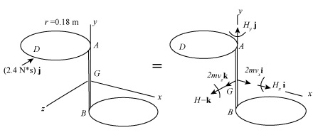
Figure-(1)
Write the expression for the impulse about point
Write the expression for the velocity of the mass centre of the system.
Here, the velocity of the mass centre in x- direction is
Calculation:
For upper plate:
Substitute
Substitute
Substitute
Substitute
For lower plate:
Substitute
Substitute
Substitute
Substitute
For assembly the inertia of the moment of both the plate is added.
Substitute
Compare coefficient of
Compare coefficient of
Compare coefficient of
Substitute
Conclusion:
The velocity of the mass centre
(b)
The angular velocity of the assembly.
Answer to Problem 18.28P
The angular velocity of the assembly is
Explanation of Solution
Write the expression for the moments about centre point
Here, the angular momentum about x- direction is
Write the expression for the angular momentum in x- direction.
Write the expression for the angular momentum in y- direction.
Write the expression for the angular momentum in z- direction.
Write the expression for the angular velocity of the assembly.
Calculation:
Substitute
Compare coefficient of
Compare coefficient of
Compare coefficient of
Substitute
Substitute
Substitute
Substitute
Substitute
Substitute
Conclusion:
The angular velocity of the assembly is
Want to see more full solutions like this?
Chapter 18 Solutions
Vector Mechanics For Engineers


- Consider a hot automotive engine, which can beapproximated as a 0.5-m-high, 0.40-m-wide, and 0.8-m-long rectangular block. The bottom surface of the block isat a temperature of 100°C and has an emissivity of 0.95.The ambient air is at 20°C, and the road surface is at25°C. Determine the rate of heat transfer from the bottomsurface of the engine block by convection and radiationas the car travels at a velocity of 80 km/h. Assume theflow to be turbulent over the entire surface because of theconstant agitation of the engine block. a) Calculate convective heat transfer coefficient (h). b) Calculate the total heat transfer ratearrow_forward8 mm- Top view -200 mm-180 mm- D B B 12 mm Side view B -8 mm D PROBLEM 1.56 In an alternative design for the structure of Prob. 1.55, a pin of 10-mm-diameter is to be used at A. Assuming that all other specifications remain unchanged, determine the allowable load P if an overall factor of safety of 3.0 is desired. PROBLEM 1.55 In the structure shown, an 8- mm-diameter pin is used at A, and 12-mm- diameter pins are used at B and D. Knowing that the ultimate shearing stress is 100 MPa at all connections and that the ultimate normal stress is 250 MPa in each of the two links joining B and D, determine the allowable load P if an overall factor of safety of 3.0 is desired. 20 mm P 8 mm- 12 mm- Front viewarrow_forwardWhere on the beam below is the Maximum Deflection likely to occur? 2P A "ती Point A Point B Point C Point D Point B or Point D ८ B पarrow_forward
- Sign in ||! PDE 321 proje X IMB321 PDF Lecture 5 X PDF Planet Ec X PDF Planet Ec X PDF PEABWX PDF meeting x PDF GSS Quo X PDF File C:/Users/KHULEKANI/Downloads/CIVE%20281%20Ass-2.pdf Draw | | All | a | Ask Copilot + 1 of 7 | D SOLUTION B PROBLEM 12.16 Block 4 has a mass of 40 kg, and block B has a mass of 8 kg. The coefficients of friction between all surfaces of contact are μ, = 0.20 H = 0.15. Knowing that P = 50 N→, determine (a) the acceleration of block B, (b) the tension in the cord. Constraint of cable: 2x + (x-x1) = x + x = constant. a+ag = 0, or aB = -a Assume that block A moves down and block B moves up. Block B: +/ΣF, = 0: NAB - WB cos 0 = 0 =ma: -T+μN + Wsin = We as g + ΣΕ We Eliminate NAB and aB- NAB B Nas HN UNA A NA -T+W(sin+μcоsе) = WB- g VD"M- g Block A: +/ΣF, = 0: NA-NAB - W₁cos + Psinė = 0 N₁ = N AB+W cose - Psin = (WB+WA)cose - Psinė ΣF=ma -T+Wsino-FAB-F + Pcos = CIVE 281 X + Ждал g Q | го || حالم ☑arrow_forwardWhere on the below beam is the Maxiumum Slope likely to occur? 120 Point A Point B Point C Point B or Point C B сarrow_forwardA very thin metallic sheet is placed between two wood plates of different thicknesses. Theplates are firmly pressed together and electricity is passed through the sheet. The exposed surfaces ofthe two plates lose heat to the ambient fluid by convection. Assume uniform heating at the interface.Neglect end effects and assume steady state.[a] Will the heat transfer through the two plates be the same? Explain.[b] Will the exposed surfaces be at the same temperature? Explainarrow_forward
- Design consideration requires that the surface of a small electronic package be maintained at atemperature not to exceed 82 o C. Noise constraints rule out the use of fans. The power dissipated inthe package is 35 watts and the surface area is 520 cm2 . The ambient temperature and surroundingwalls are assumed to be at 24 o C. The heat transfer coefficient is estimated to be 9.2 W/m2- oC andsurface emissivity is 0.7. Will the package dissipate the required power without violating designconstraints?arrow_forwardConsider radiation from a small surface at 100 oC which is enclosed by a much larger surface at24 o C. Determine the percent increase in the radiation heat transfer if the temperature of the smallsurface is doubled.arrow_forwardA small electronic package with a surface area of 820 cm2 is placed in a room where the airtemperature is 28 o C. The heat transfer coefficient is 7.3 W/m2 - o C. You are asked to determine if it isjustified to neglect heat loss from the package by radiation. Assume a uniform surface temperature of78 o C and surface emissivity of 0.65 Assume further that room’s walls and ceiling are at a uniformtemperature of 16 o C.arrow_forward
- A hollow metal sphere of outer radius or = 2 cm is heated internally with a variable output electricheater. The sphere loses heat from its surface by convection and radiation. The heat transfercoefficient is 22 W/ m2 - o C and surface emissivity is 0.92. The ambient fluid temperature is 20 o C andthe surroundings temperature is 14 oC. Construct a graph of the surface temperature corresponding toheating rates ranging from zero to 100 watts. Assume steady state. Use a simplified model forradiation exchange based on a small gray surface enclosed by a much larger surface at 14 o C.arrow_forward2. A program to make the part depicted in Figure 26.A has been created, presented in figure 26.B, but some information still needs to be filled in. Compute the tool locations, depths, and other missing information to present a completed program. (Hint: You may have to look up geometry for the center drill and standard 0.5000 in twist drill to know the required depth to drill). Dashed line indicates - corner of original stock Intended toolpath-tangent - arc entry and exit sized to programmer's judgment 026022 (Slot and Drill Part) (Setup Instructions. (UNITS: Inches (WORKPIECE MAT'L: SAE 1020 STEEL (Workpiece: 3.25 x 2.00 x0.75 in. Plate (PRZ Location G54: ( XY 0.0 Upper Left of Fixture ( TOP OF PART 2-0 (Tool List: ) ( T04 T02 0.500 IN 4 FLUTE FLAT END MILL) #4 CENTER DRILL ' T02 0.500 TWIST DRILL N010 GOO G90 G17 G20 G49 G40 G80 G54 N020 M06 T02 (0.5 IN 4-FLUTE END MILL) R0.750 N030 S760 M03 G00 x N040 043 H02 2 Y (P1) (RAPID DOWN -TLO) P4 NO50 MOB (COOLANT ON) N060 G01 X R1.000 N070…arrow_forward6–95. The reaction of the ballast on the railway tie can be assumed uniformly distributed over its length as shown. If the wood has an allowable bending stress of σallow=1.5 ksi, determine the required minimum thickness t of the rectangular cross section of the tie to the nearest 18 in. Please include all steps. Also if you can, please explain how you found Mmax using an equation rather than using just the moment diagram. Thank you!arrow_forward
 Elements Of ElectromagneticsMechanical EngineeringISBN:9780190698614Author:Sadiku, Matthew N. O.Publisher:Oxford University Press
 Mechanics of Materials (10th Edition)Mechanical EngineeringISBN:9780134319650Author:Russell C. HibbelerPublisher:PEARSON
 Thermodynamics: An Engineering ApproachMechanical EngineeringISBN:9781259822674Author:Yunus A. Cengel Dr., Michael A. BolesPublisher:McGraw-Hill Education
 Control Systems EngineeringMechanical EngineeringISBN:9781118170519Author:Norman S. NisePublisher:WILEY
 Mechanics of Materials (MindTap Course List)Mechanical EngineeringISBN:9781337093347Author:Barry J. Goodno, James M. GerePublisher:Cengage Learning
 Engineering Mechanics: StaticsMechanical EngineeringISBN:9781118807330Author:James L. Meriam, L. G. Kraige, J. N. BoltonPublisher:WILEY