Concept explainers
Videos
(a)
The couple
Answer to Problem 18.77P
The couple
Explanation of Solution
Given information:
The total mass is
Write the expression for the sum of the moment acting on the body along x -direction.
Here, the product of the moment of the inertia of
Write the expression for the sum of the moment acting on the body along y -direction.
Write the expression for the sum of the moment acting on the body along z -direction.
Here, the moment of the inertia along the z -direction is
Draw the diagram for the for the sheet metal component.
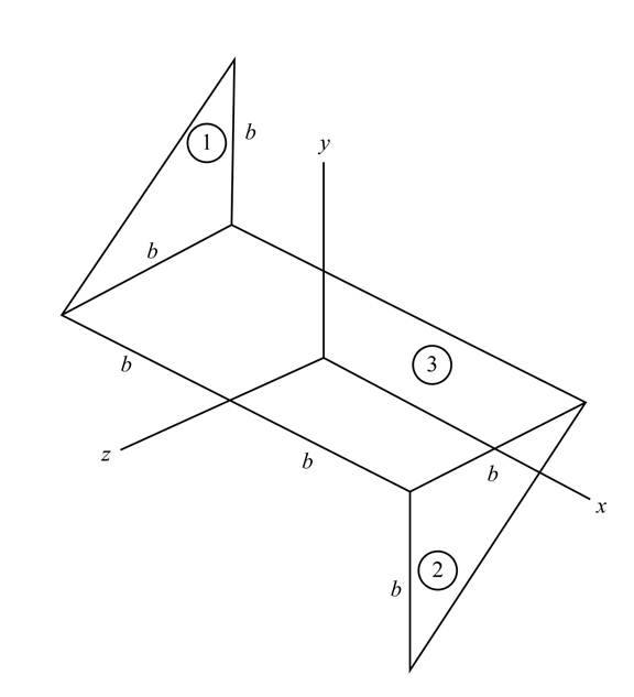
Figure-(1)
Write the expression for the area of the section 1 shown in the Figure-(1).
Here, the constant dimension is
Write the expression for the area of the section 2 shown in the Figure-(1).
Write the expression for the area of the section 3 shown in the Figure-(1).
Write the expression for the total area of the sheet.
Substitute
Write the expression of mass per unit area of the system.
Here, the mass of the sheet metal component is
Write the expression for the variation of the
Here, the coordinate of the considered point is
The below figure represent the schematic diagram of the elemental strip of section 1.
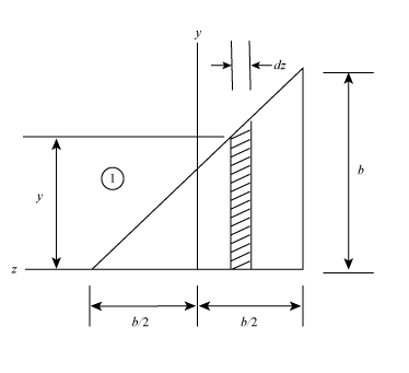
Figure-(2)
Write the expression for the distance of the centroid of the element from the
Write the expression for the mass of the elemental strip.
Here, the area of the elemental strip is
Write the expression for the moment of inertia of the element with respect to z- axis.
Write the expression for the moment of the inertia of the section 1.
Write the expression for the product of moment of inertia of the plane
Write the expression for the product of moment of inertia of the plane
Write the expression for the variation of the
The below figure represent the schematic diagram of the elemental strip of section 2.
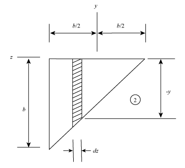
Figure-(3)
Write the expression for the mass of the elemental strip of section 2.
Write the expression for the moment of the inertia of the section 2.
Write the expression for the product of moment of inertia of the plane
Write the expression for the product of moment of inertia of the plane
Write the expression of mass per unit area of the section3 in Figure-(1).
Here, the mass of the rectangular sheet metal component is
Write the expression for the moment of the inertia of the section 3.
The product moment of the inertia for the plane
Write the expression for the moment of the inertia of the whole system.
Write the expression for the product of moment of inertia of the whole system.
Write the expression for the product of moment of inertia of the whole system.
Draw the diagram for the system to shows the action of forces on the system.
Figure-(4)
Here, the reaction on the point
Calculation:
Substitute
Substitute
Substitute
Substitute
Substitute
Substitute
Substitute
Substitute
Substitute
Conclusion:
The couple
(b)
The dynamic reactions at
The dynamic reactions at
Answer to Problem 18.77P
The dynamic reactions at
The dynamic reactions at
Explanation of Solution
Write the expression for the dynamic reaction at point
Write the expression for the dynamic reaction at point
Write the expression for the reaction forces along the y- direction.
Write the expression for the reaction forces along the x- direction.
Write the expression for the sum of the moment acting on the body along x -direction.
Here, distance between the point
Write the expression for the sum of the moment acting on the body along y -direction.
Calculation:
Substitute
Substitute
Substitute
Substitute
Substitute
Substitute
Substitute
Substitute
Substitute
Substitute
Substitute
Substitute
Substitute
Substitute
Conclusion:
The dynamic reactions at
The dynamic reactions at
Want to see more full solutions like this?
Chapter 18 Solutions
Vector Mechanics For Engineers


- I need help with a MATLAB code. This code just keeps running and does not give me any plots. I even reduced the tolerance from 1e-9 to 1e-6. Can you help me fix this? Please make sure your solution runs. % Initial Conditions rev = 0:0.001:2; g1 = deg2rad(1); g2 = deg2rad(3); g3 = deg2rad(6); g4 = deg2rad(30); g0 = deg2rad(0); Z0 = 0; w0 = [0; Z0*cos(g0); -Z0*sin(g0)]; Z1 = 5; w1 = [0; Z1*cos(g1); -Z1*sin(g1)]; Z2 = 11; w2 = [0; Z2*cos(g2); -Z2*sin(g2)]; [v3, psi3, eta3] = Nut_angle(Z2, g2, w2); plot(v3, psi3) function dwedt = K_DDE(~, w_en) % Extracting the initial condtions to a variable % Extracting the initial condtions to a variable w = w_en(1:3); e = w_en(4:7); Z = w_en(8); I = 0.060214; J = 0.015707; x = (J/I) - 1; y = Z - 1; s = Z; % Kinematic Differential Equations dedt = zeros(4,1); dedt(1) = pi*(e(3)*(s-w(2)-1) + e(2)*w(3) + e(4)*w(1)); dedt(2) = pi*(e(4)*(w(2)-1-s) + e(3)*w(1) - e(1)*w(3)); dedt(3) = pi*(-e(1)*(s-w(2)-1) - e(2)*w(1) + e(4)*w(3));…arrow_forwardalpha 1 is not zero alpha 1 can equal alpha 2 use velocity triangle to solve for alpha 1 USE MATLAB ONLY provide typed code solve for velocity triangle and dont provide copied answer Turbomachienery . GIven: vx = 185 m/s, flow angle = 60 degrees, (leaving a stator in axial flow) R = 0.5, U = 150 m/s, b2 = -a3, a2 = -b3 Find: velocity triangle , a. magnitude of abs vel leaving rotor (m/s) b. flow absolute angles (a1, a2, a3) 3. flow rel angles (b2, b3) d. specific work done e. use code to draw vel. diagram Use this code for plot % plots Velocity Tri. in Ch4 function plotveltri(al1,al2,al3,b2,b3) S1L = [0 1]; V1x = [0 0]; V1s = [0 1*tand(al3)]; S2L = [2 3]; V2x = [0 0]; V2s = [0 1*tand(al2)]; W2s = [0 1*tand(b2)]; U2x = [3 3]; U2y = [1*tand(b2) 1*tand(al2)]; S3L = [4 5]; V3x = [0 0]; V3r = [0 1*tand(al3)]; W3r = [0 1*tand(b3)]; U3x = [5 5]; U3y = [1*tand(b3) 1*tand(al3)]; plot(S1L,V1x,'k',S1L,V1s,'r',... S2L,V2x,'k',S2L,V2s,'r',S2L,W2s,'b',U2x,U2y,'g',...…arrow_forward3. Find a basis of eigenvectors and diagonalize. 4 0 -19 7 a. b. 1-42 16 12-20 [21-61arrow_forward
- 2. Find the eigenvalues. Find the corresponding eigenvectors. 6 2 -21 [0 -3 1 3 31 a. 2 5 0 b. 3 0 -6 C. 1 1 0 -2 0 7 L6 6 0 1 1 2. (Hint: λ = = 3)arrow_forwardUSE MATLAB ONLY provide typed code solve for velocity triangle and dont provide copied answer Turbomachienery . GIven: vx = 185 m/s, flow angle = 60 degrees, (leaving a stator in axial flow) R = 0.5, U = 150 m/s, b2 = -a3, a2 = -b3 Find: velocity triangle , a. magnitude of abs vel leaving rotor (m/s) b. flow absolute angles (a1, a2, a3) 3. flow rel angles (b2, b3) d. specific work done e. use code to draw vel. diagram Use this code for plot % plots Velocity Tri. in Ch4 function plotveltri(al1,al2,al3,b2,b3) S1L = [0 1]; V1x = [0 0]; V1s = [0 1*tand(al3)]; S2L = [2 3]; V2x = [0 0]; V2s = [0 1*tand(al2)]; W2s = [0 1*tand(b2)]; U2x = [3 3]; U2y = [1*tand(b2) 1*tand(al2)]; S3L = [4 5]; V3x = [0 0]; V3r = [0 1*tand(al3)]; W3r = [0 1*tand(b3)]; U3x = [5 5]; U3y = [1*tand(b3) 1*tand(al3)]; plot(S1L,V1x,'k',S1L,V1s,'r',... S2L,V2x,'k',S2L,V2s,'r',S2L,W2s,'b',U2x,U2y,'g',... S3L,V3x,'k',S3L,V3r,'r',S3L,W3r,'b',U3x,U3y,'g',...... 'LineWidth',2,'MarkerSize',10),...…arrow_forwardUSE MATLAB ONLY provide typed code solve for velocity triangle and dont provide copied answer Turbomachienery . GIven: vx = 185 m/s, flow angle = 60 degrees, R = 0.5, U = 150 m/s, b2 = -a3, a2 = -b3 Find: velocity triangle , a. magnitude of abs vel leaving rotor (m/s) b. flow absolute angles (a1, a2, a3) 3. flow rel angles (b2, b3) d. specific work done e. use code to draw vel. diagram Use this code for plot % plots Velocity Tri. in Ch4 function plotveltri(al1,al2,al3,b2,b3) S1L = [0 1]; V1x = [0 0]; V1s = [0 1*tand(al3)]; S2L = [2 3]; V2x = [0 0]; V2s = [0 1*tand(al2)]; W2s = [0 1*tand(b2)]; U2x = [3 3]; U2y = [1*tand(b2) 1*tand(al2)]; S3L = [4 5]; V3x = [0 0]; V3r = [0 1*tand(al3)]; W3r = [0 1*tand(b3)]; U3x = [5 5]; U3y = [1*tand(b3) 1*tand(al3)]; plot(S1L,V1x,'k',S1L,V1s,'r',... S2L,V2x,'k',S2L,V2s,'r',S2L,W2s,'b',U2x,U2y,'g',... S3L,V3x,'k',S3L,V3r,'r',S3L,W3r,'b',U3x,U3y,'g',...... 'LineWidth',2,'MarkerSize',10),... axis([-1 6 -4 4]), ...…arrow_forward
- The answer should equal to 1157. Please sent me the solution. Thank you!arrow_forwardBONUS: If the volume of the 8cm x 6.5cm x 6cm Block of Aluminum was 312cm3 before machining, find how much material was removed when the fixture below was machined. +2 2.00 cm 6.00 cm 2.50 cm 6.50 cm 1.00 cm 2.50 cm 11.00 cm 8.00 cm 30 CP 9411 FL.4) (m² 1157 Area of triangle = 1/2*B*H Area of circle = лR² Circumference of a circle = 2πR 6.00 cm 6.50 cm 1.50 cm Radius 1.50 cm 1.00 cmarrow_forwardConsider a 5m by 5m wet concret patio with an average water film thickness of .2mm. Now wind at 50 km/h is blowing over the surface. If the air is at 1 atm, 15oC and 35 percent relative humidity, determine how long it will take for the patio to completely dry.arrow_forward
- 70. Compute the number of cubic centimeters of iron required for the cast-iron plate shown. The plate is 3.50 centimeters thick. Round the answer to the nearest cubic centimeter. 50.0 cm 40.0 cm Radius 150° 115.0 cm- 81.0 cmarrow_forwardLaw of Sines Solve the following problems using the Law of Sin 7. Find side x. All dimensions are in inches. -°-67°-37° 81° x Sin A 8.820 X 67°00' 32°00' a sin A b C sin B sin Carrow_forward35. a. Determine B. b. Determine side b. c. Determine side c. 5.330 in.- ZB 73°30'arrow_forward
 Elements Of ElectromagneticsMechanical EngineeringISBN:9780190698614Author:Sadiku, Matthew N. O.Publisher:Oxford University Press
 Mechanics of Materials (10th Edition)Mechanical EngineeringISBN:9780134319650Author:Russell C. HibbelerPublisher:PEARSON
 Thermodynamics: An Engineering ApproachMechanical EngineeringISBN:9781259822674Author:Yunus A. Cengel Dr., Michael A. BolesPublisher:McGraw-Hill Education
 Control Systems EngineeringMechanical EngineeringISBN:9781118170519Author:Norman S. NisePublisher:WILEY
 Mechanics of Materials (MindTap Course List)Mechanical EngineeringISBN:9781337093347Author:Barry J. Goodno, James M. GerePublisher:Cengage Learning
 Engineering Mechanics: StaticsMechanical EngineeringISBN:9781118807330Author:James L. Meriam, L. G. Kraige, J. N. BoltonPublisher:WILEY