
Videos
(a)
To plot: The graph of current in the transistor as a function of the input voltage for given range.
(a)
Answer to Problem 16.36P
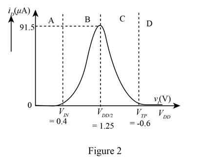
The required plot is shown in Figure 2
Explanation of Solution
Calculation:
The given diagram is shown in Figure 1.

Consider the case when the input voltage is equal to zero.
The NMOS device is in the cutoff region the drain current of the transistor is zero and when the PMOS transistor is in the non-saturation region its drain current is also zero.
Consider the case when
The PMOS transistor in the Non-saturation and the NMOS just started to conduct and then enter in the saturation mode.
The expression for the drain current of the NMOS transistor is given by,
The expression for the drain current of the PMOS transistor is given by,
The CMOS drain current is due to the drain current of the NMOS alone and is given by,
Substitute
Substitute
The tale to determine the value of the output current for the different value of the output voltage is shown below.
The required table is shown in Table 1
Table 1
Consider the case when the input voltage is
The expression for the drain current of the PMOS in saturation is given by,
The expression for the drain current of the NMOS in non-saturation is given by,
The CMOS current depends only on the current through the drain current of the PMOS and is given by,
Substitute
Substitute
The table for the output current for the different values of the input voltage is shown below.
The required table is shown in Table 2
Table 2
Consider the case when the input voltage is given by,
For the above case the NMOS is in non-saturation region and the drain current is zero. The PMOS is in cut off and the drain current zero as the circuit is open.
The drain current when the input voltage is zero and the circuit is opened is given by,
The plot for the CMOS drain current against the input voltage from the values of table 1 and table 2 is shown below.
The required plot is shown in Figure 2
Conclusion:
Therefore, the required plot is shown in Figure 2.
(b)
To plot: The current in the transistor as a function fo the input voltage.
(b)
Answer to Problem 16.36P
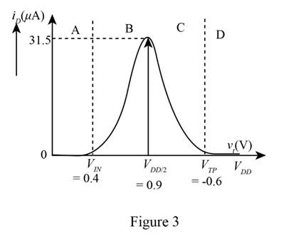
The required plot is shown in Figure 3
Explanation of Solution
Calculation:
Consider the case when the voltage
Consider the input voltage as
Consider the case when the input voltage is
The expression for the drain current of the NMOS is given by,
The expression for the drain current of the PMOS transistor is given by,
The CMOS drain current is due to the drain current of the NMOS alone and is given by,
Substitute
Substitute
The table for the output current for the different values of the input voltage is shown below.
The required table is shown in Table 3
Table 3
Consider the case when the input voltage
The PMOS transistor is in the non-saturation and the NMOS just beings to conduct and then goes to saturation.
The expression for the drain current of the NMOS is given by,
The expression for the drain current of the PMOS transistor is given by,
The CMOS drain current is due to the drain current of the PMOS alone and is given by,
Substitute
Substitute
The table for the output current for the different values of the input voltage is shown below.
The required table is shown in Table 4
Table 4
Consider the case when the input voltage is
The plot between the drain current and the input voltage from table 3 and table 4 is shown below.
The required plot is shown in Figure 3
Conclusion:
Therefore, the required plot is shown in Figure 3
Want to see more full solutions like this?
Chapter 16 Solutions
Microelectronics: Circuit Analysis and Design


- Q2-A)- Enumerate the various losses in transformer. Explain how each loss varies with (Load current, supply voltage). B)- Draw the pharos diagram at load on primary side.arrow_forwardQ2- What are the parameters and loss that can be determined during open-circuit test of singlephase transformer. Draw the circuit diagram of open-circuit test and explain how can you calculate the Parameters and loss.arrow_forwardQ2-Drive the condition of maximum efficiency of single-phase transformer. Q1- A 5 KVA, 500/250 V ,50 Hz, single phase transformer gave the following reading: O.C. Test: 250 V,2 A, 50 W (H.V. side open) S.C. Test: 25 V10 A, 60 W (L.V. side shorted) Determine: i) The efficiency on full load, 0.8 lagging p.f. ii) Draw the equivalent circuit referred to primary and insert all the values it.arrow_forward
- Q2- Describe various losses in transformer. Explain how each loss varies with load current, supply voltagearrow_forwardQ1-A 12 KVA, 440/ 220 V, 50 Hz single phase transformer has 275 secondary turns. The no load current of transformer is 2A at power factor 0.375 when connected to 220 V, 50 Hz supply. The full load copper loss is 198.3 watt. Calculate a) Maximum value of flux in the core. b) Maximum efficiency at 0.8 lagging p.f c) KVA supply at maximum efficiencyarrow_forwardQ1- A 5 KVA, 240/120 volt, single-phase transformer supplies rated current to a load at 120 V. Determine the magnitude of the load impedance as seen from the input terminals of the transformer. Ans. 11.52arrow_forward
- Q1- A single phase transformer consumes 2 A on no load at p.f. 0.208 lagging. The turns ratio is 2/1 (step down). If the loads on the secondary is 25 A at a p.f. 0.866 lagging. Find the primary current and power factor.arrow_forwardI am seeking ideas or references regarding the auxiliary power output for a trolley. I’ve encountered difficulties finding information online about the power output for lights, buzzers, and speakers. Specifically, I am interested in the following questions: How many lights, buzzers, and speakers can a trolley approximately 48 feet in length accommodate?How can I determine their rated power?Any guidance or resources you can provide would be greatly appreciated. Thank you!arrow_forward5. Three single-phase transformers rated at 250 kVA, 7200 V/600 V, 60 Hz, are connected in wye-delta on a 12470 V, 3-phase line. If the load is 450 kVA, calculate the following currents: (1) In the incoming and outgoing transmission lines (2) In the primary and secondary windings (3) If this transformer is used to raise the voltage of a 3-phase, 600 V line to 7.2 kV. (a) How must they be connected? (b) Calculate the line currents for a 600 kVA load. (c) Calculate the corresponding primary and secondary currents.arrow_forward
 Introductory Circuit Analysis (13th Edition)Electrical EngineeringISBN:9780133923605Author:Robert L. BoylestadPublisher:PEARSON
 Delmar's Standard Textbook Of ElectricityElectrical EngineeringISBN:9781337900348Author:Stephen L. HermanPublisher:Cengage Learning
 Programmable Logic ControllersElectrical EngineeringISBN:9780073373843Author:Frank D. PetruzellaPublisher:McGraw-Hill Education
 Fundamentals of Electric CircuitsElectrical EngineeringISBN:9780078028229Author:Charles K Alexander, Matthew SadikuPublisher:McGraw-Hill Education
 Electric Circuits. (11th Edition)Electrical EngineeringISBN:9780134746968Author:James W. Nilsson, Susan RiedelPublisher:PEARSON
 Engineering ElectromagneticsElectrical EngineeringISBN:9780078028151Author:Hayt, William H. (william Hart), Jr, BUCK, John A.Publisher:Mcgraw-hill Education,