Concept explainers
Videos
The remote manipulator system (RMS) shown is used to deploy payloads from the cargo bay of space shuttles. At the instant shown, the whole RMS is rotating at the constant rate
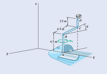
Fig. P15.217
Want to see the full answer?
Check out a sample textbook solution
Chapter 15 Solutions
Vector Mechanics for Engineers: Dynamics


- Mych CD 36280 kg. 0.36 givens Tesla truck frailer 2017 Model Vven 96154kph ronge 804,5km Cr Powertrain Across PHVAC rwheel 0.006 0.88 9M² 2 2kW 0.55M ng Zg Prated Trated Pair 20 0.95 1080 kW 1760 Nm 1,2 determine the battery energy required to meet the range when fully loaded determine the approximate time for the fully-loaded truck-trailor to accelerate from 0 to 60 mph while Ignoring vehicle load forcesarrow_forward12-217. The block B is sus- pended from a cable that is at- tached to the block at E, wraps around three pulleys, and is tied to the back of a truck. If the truck starts from rest when ID is zero, and moves forward with a constant acceleration of ap = 0.5 m/s², determine the speed of the block at D the instant x = 2 m. Neglect the size of the pulleys in the calcu- lation. When xƊ = 0, yc = 5 m, so that points C and D are at the Prob. 12-217 5 m yc =2M Xparrow_forwardsolve both and show matlab code auto controlsarrow_forward
- 12-82. The roller coaster car trav- els down the helical path at con- stant speed such that the paramet- ric equations that define its posi- tion are x = c sin kt, y = c cos kt, z = h - bt, where c, h, and b are constants. Determine the mag- nitudes of its velocity and accelera- tion. Prob. 12-82 Narrow_forwardGiven: = refueling Powertran SOURCE EMISSIONS vehide eff eff gasoline 266g co₂/kwh- HEV 0.90 0.285 FLgrid 411ilg Co₂/kWh 41111gCo₂/kWh EV 0.85 0.80 Production 11x10% og CO₂ 13.7 x 10°g CO₂ A) Calculate the breakeven pont (in km driven) for a EV against on HEV in Florida of 0.1kWh/kM Use a drive cycle conversion 5) How efficient would the powertrain of the HEV in this example have to be to break even with an EV in Florida after 150,000 Miles of service (240,000) km Is it plausible to achieve the answer from pert b Consideans the HaXINERY theoretical efficiency of the Carnot cycle is 5020 and there are additional losses of the transMISSION :- 90% efficiency ? c A what do you conclude is the leading factor in why EVs are less emissive than ICE,arrow_forwardsolve autocontrolsarrow_forward
- Problem 3.21P: Air at 100F(38C) db,65F(18C) wb, and sea-level pressure is humidified adiabatically with steam. The steam supplied contains 20 percent moisture(quality of 0.80) at 14.7psia(101.3kpa). The air is humidified to 60 percent relative humidity. Find the dry bulb temperature of the humidified air using (a)chart 1a or 1b and (b) the program PSYCH.arrow_forwardPUNTO 4. calculate their DoF using Gruebler's formula. PUNTO 5. Groundarrow_forwardPUNTO 2. PUNTO 3. calculate their DoF using Gruebler's formula. III IAarrow_forward
- calculate their DoF using Gruebler's formula. PUNTO 6. PUNTO 7. (Ctrl)arrow_forwardA pump delivering 230 lps of water at 30C has a 300-mm diameter suction pipe and a 254-mm diameter discharge pipe as shown in the figure. The suction pipe is 3.5 m long and the discharge pipe is 23 m long, both pipe's materials are cast iron. The water is delivered 16m above the intake water level. Considering head losses in fittings, valves, and major head loss. a) Find the total dynamic head which the pump must supply. b)It the pump mechanical efficiency is 68%, and the motor efficiency is 90%, determine the power rating of the motor in hp.given that: summation of K gate valve = 0.25check valve=390 degree elbow= 0.75foot valve= 0.78arrow_forwardA pump delivering 230 lps of water at 30C has a 300-mm diameter suction pipe and a 254-mm diameter discharge pipe as shown in the figure. The suction pipe is 3.5 m long and the discharge pipe is 23 m long, both pipe's materials are cast iron. The water is delivered 16m above the intake water level. Considering head losses in fittings, valves, and major head loss. a) Find the total dynamic head which the pump must supply. b)It the pump mechanical efficiency is 68%, and the motor efficiency is 90%, determine the power rating of the motor in hp.arrow_forward
 Elements Of ElectromagneticsMechanical EngineeringISBN:9780190698614Author:Sadiku, Matthew N. O.Publisher:Oxford University Press
 Mechanics of Materials (10th Edition)Mechanical EngineeringISBN:9780134319650Author:Russell C. HibbelerPublisher:PEARSON
 Thermodynamics: An Engineering ApproachMechanical EngineeringISBN:9781259822674Author:Yunus A. Cengel Dr., Michael A. BolesPublisher:McGraw-Hill Education
 Control Systems EngineeringMechanical EngineeringISBN:9781118170519Author:Norman S. NisePublisher:WILEY
 Mechanics of Materials (MindTap Course List)Mechanical EngineeringISBN:9781337093347Author:Barry J. Goodno, James M. GerePublisher:Cengage Learning
 Engineering Mechanics: StaticsMechanical EngineeringISBN:9781118807330Author:James L. Meriam, L. G. Kraige, J. N. BoltonPublisher:WILEY