Concept explainers
Videos
In Prob. 15.199, determine (a) the common angular acceleration of gears A and B, (b) the acceleration of the tooth of gear A that is in contact with gear C at point 1.
(a)
The common angular acceleration of the gears
Answer to Problem 15.200P
The common angular acceleration of the gears
Explanation of Solution
Given Information:
The angular velocity of the gear
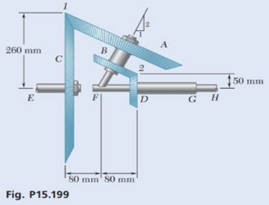
Draw the schematic diagram of the given system.
Figure-(1)
Write the expression for the velocity of point 1.
Here, the angular velocity of the gear
Write the expression for the velocity of point 1 when gear
Here, the angular velocity of the shaft unit carries gear
Write the expression for the velocity of point 2.
Here, the angular velocity of the gear
Write the expression for the velocity of point 2 when gear
Write the expression for the angular velocity of the inclined shaft unit which carries gear
Here, the angular velocity of the shaft in x- direction is
Draw the diagram to show the motion of the shaft is
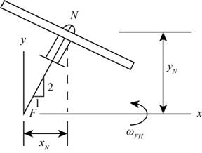
Figure-(2)
Write the expression for the velocity of point
Here, the position vector at point
Write the expression for the velocity at point
Here, the angular velocity of shaft
Write the expression for the common angular acceleration of the gear
Calculation:
Consider the unit vector along
From Figure-(1) the coordinate of the point 1 at the intersection of the gears
From Figure-(1) the coordinate of the point 2 at the intersection of the gears
Since, the shaft
Substitute
Substitute
Substitute
Compare the terms along the x- direction in Equation (X).
Compare the terms along the z- direction in Equation (X).
Since, the shaft
Substitute
Substitute
Substitute
Compare the terms along the z- direction in Equation (X).
Substitute
Substitute
Substitute
From Figure-(2) the coordinate of the point
Substitute
Substitute
Substitute
Substitute
Conclusion:
The common angular acceleration of the gear
(b)
The acceleration of the tooth of the gear
Answer to Problem 15.200P
The acceleration of the tooth of the gear
Explanation of Solution
Write the expression for the acceleration of the gear
Calculation:
Substitute
Conclusion:
The acceleration of the tooth of the gear
Want to see more full solutions like this?
Chapter 15 Solutions
Vector Mechanics for Engineers: Dynamics


- This is an exam review question. The answer is Pmin = 622.9 lb but whyarrow_forwardPlease do not use any AI tools to solve this question. I need a fully manual, step-by-step solution with clear explanations, as if it were done by a human tutor. No AI-generated responses, please.arrow_forwardPlease do not use any AI tools to solve this question. I need a fully manual, step-by-step solution with clear explanations, as if it were done by a human tutor. No AI-generated responses, please.arrow_forward
- Please do not use any AI tools to solve this question. I need a fully manual, step-by-step solution with clear explanations, as if it were done by a human tutor. No AI-generated responses, please.arrow_forwardThis is an old practice exam. Fce = 110lb and FBCD = 62 lb but whyarrow_forwardQuiz/An eccentrically loaded bracket is welded to the support as shown in Figure below. The load is static. The weld size for weld w1 is h1 = 4mm, for w2 h2 = 6mm, and for w3 is h3 =6.5 mm. Determine the safety factor (S.f) for the welds. F=29 kN. Use an AWS Electrode type (E100xx). 163 mm S 133 mm 140 mm Please solve the question above I solved the question but I'm sure the answer is wrong the link : https://drive.google.com/file/d/1w5UD2EPDiaKSx3W33aj Rv0olChuXtrQx/view?usp=sharingarrow_forward
- Q2: (15 Marks) A water-LiBr vapor absorption system incorporates a heat exchanger as shown in the figure. The temperatures of the evaporator, the absorber, the condenser, and the generator are 10°C, 25°C, 40°C, and 100°C respectively. The strong liquid leaving the pump is heated to 50°C in the heat exchanger. The refrigerant flow rate through the condenser is 0.12 kg/s. Calculate (i) the heat rejected in the absorber, and (ii) the COP of the cycle. Yo 8 XE-V lo 9 Pc 7 condenser 5 Qgen PG 100 Qabs Pe evaporator PRV 6 PA 10 3 generator heat exchanger 2 pump 185 absorberarrow_forwardQ5:(? Design the duct system of the figure below by using the balanced pressure method. The velocity in the duct attached to the AHU must not exceed 5m/s. The pressure loss for each diffuser is equal to 10Pa. 100CFM 100CFM 100CFM ☑ ☑ 40m AHU -16m- 8m- -12m- 57m 250CFM 40m -14m- 26m 36m ☑ 250CFMarrow_forwardA mass of ideal gas in a closed piston-cylinder system expands from 427 °C and 16 bar following the process law, pv1.36 = Constant (p times v to the power of 1.36 equals to a constant). For the gas, initial : final pressure ratio is 4:1 and the initial gas volume is 0.14 m³. The specific heat of the gas at constant pressure, Cp = 0.987 kJ/kg-K and the specific gas constant, R = 0.267 kJ/kg.K. Determine the change in total internal energy in the gas during the expansion. Enter your numerical answer in the answer box below in KILO JOULES (not in Joules) but do not enter the units. (There is no expected number of decimal points or significant figures).arrow_forward
- my ID# 016948724. Please solve this problem step by steparrow_forwardMy ID# 016948724 please find the forces for Fx=0: fy=0: fz=0: please help me to solve this problem step by steparrow_forwardMy ID# 016948724 please solve the proble step by step find the forces fx=o: fy=0; fz=0; and find shear moment and the bending moment diagran please draw the diagram for the shear and bending momentarrow_forward
 Principles of Heat Transfer (Activate Learning wi...Mechanical EngineeringISBN:9781305387102Author:Kreith, Frank; Manglik, Raj M.Publisher:Cengage Learning
 International Edition---engineering Mechanics: St...Mechanical EngineeringISBN:9781305501607Author:Andrew Pytel And Jaan KiusalaasPublisher:CENGAGE L
 Precision Machining Technology (MindTap Course Li...Mechanical EngineeringISBN:9781285444543Author:Peter J. Hoffman, Eric S. Hopewell, Brian JanesPublisher:Cengage Learning
 Understanding Motor ControlsMechanical EngineeringISBN:9781337798686Author:Stephen L. HermanPublisher:Delmar Cengage Learning
 Automotive Technology: A Systems Approach (MindTa...Mechanical EngineeringISBN:9781133612315Author:Jack Erjavec, Rob ThompsonPublisher:Cengage Learning
 Welding: Principles and Applications (MindTap Cou...Mechanical EngineeringISBN:9781305494695Author:Larry JeffusPublisher:Cengage Learning