Vector Mechanics for Engineers: Dynamics
11th Edition
ISBN: 9780077687342
Author: Ferdinand P. Beer, E. Russell Johnston Jr., Phillip J. Cornwell, Brian Self
Publisher: McGraw-Hill Education
expand_more
expand_more
format_list_bulleted
Concept explainers
Videos
Textbook Question
Chapter 15, Problem 15.250RP
A baseball pitching machine is designed to deliver a baseball with a ball speed of 70 mph and a ball rotation of 300 rpm clockwise. Knowing that there is no slipping between the wheels and the baseball during the ball launch, determine the angular velocities of wheels A and B.
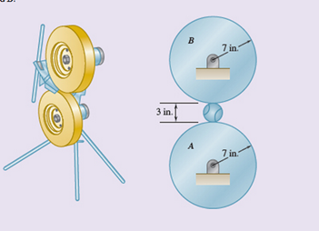
Fig. P15.250
Expert Solution & Answer
Want to see the full answer?
Check out a sample textbook solution
Students have asked these similar questions
In MATLAB, can you help me simulate an orbit under earth J2 perturbation with the Milankovich orbital elements? Also, can you check to see if they fit the Milankovich constraint equaiton?
8. All of the members in the Warren truss of Figure 8 are of length 10 ft. Use the method of
sections to determine the forces in the members BD,CD,CE.
B
A
C
D
E
F
G
2000 lb
3000 lb
5000 lb
Figure 8
H
An acrobat is walking on a tightrope of length L
=20.1 m attached to supports A and B at a
distance of 20.0 m apart. The combined weight
of the acrobat and his balancing pole is 900 N,
and the friction between his shoes and the rope
is large enough to prevent him from slipping.
Neglecting the weight of the rope and any
elastic deformation, determine the deflection (y)
and the tension in portion AC and BC of the
rope for values of x from 0.5 m to 10 m using
0.5 m increments.
1. Determine the maximum deflection (y) in
the rope.
2. Plot tension of AC and BC vs. x (on the
same plot with x on the x-axis). Turn in the
plot and the table of x, TAC, and TBC (clearly
label each).
A
C
20.0 m
B
Chapter 15 Solutions
Vector Mechanics for Engineers: Dynamics
Ch. 15.1 - A rectangular plate swings from arms of equal...Ch. 15.1 - Knowing that wheel A rotates with a constant...Ch. 15.1 - The brake drum is attached to a lager flywheel...Ch. 15.1 - The motion of an oscillation flvdee1 is defined by...Ch. 15.1 - The motion of an oscillation flywheel is defined...Ch. 15.1 - The rotor of a gas turbine is rotating at a speed...Ch. 15.1 - A small grinding wheel is attached to the shaft of...Ch. 15.1 - A connecting rod is supported by a knife-edge at...Ch. 15.1 - When studying whiplash resulting from rear-end...Ch. 15.1 - The angular acceleration of an oscillating disk is...
Ch. 15.1 - The angular acceleration of a shaft is defined by...Ch. 15.1 - The bent rod ABCD rotates about a line joining...Ch. 15.1 - In Prob. 15.10, determine the velocity and...Ch. 15.1 - The rectangular block shown rotates about the...Ch. 15.1 - The rectangular block shown rotates about the...Ch. 15.1 - A circular plate of 120-mm radius is supported by...Ch. 15.1 - In Prob. 15.14, determine the velocity and...Ch. 15.1 - The earth makes one complete revolution around the...Ch. 15.1 - The earth makes one complete revolution on its...Ch. 15.1 - A series of small machine components being moved...Ch. 15.1 - A series of small machine components being moved...Ch. 15.1 - The belt sander shown is initially at rest. If the...Ch. 15.1 - The rated speed of drum B of the belt sander shown...Ch. 15.1 - The two pulleys shown may be operated with the V...Ch. 15.1 - Three belts move over tow pulleys without slipping...Ch. 15.1 - gear reduction system consists of three gears A,...Ch. 15.1 - A belt is pulled to the right between cylinders A...Ch. 15.1 - Ring C has an inside radius of 55 mm and an...Ch. 15.1 - Ring B has an inside radius r2and hangs from the...Ch. 15.1 - A plastic film moves over two drums. During a 4-s...Ch. 15.1 - Cylinder A is moving downward with a velocity of 3...Ch. 15.1 - The system shown is held at rest by the...Ch. 15.1 - A load is to be raised 20 ft by the hoisting...Ch. 15.1 - A simple friction drive consists of two disks A...Ch. 15.1 - Two friction wheels A and B are both rotating...Ch. 15.1 - Two friction disks A and B are to be brought into...Ch. 15.1 - Two friction disks A and B are brought into...Ch. 15.1 - Steel tape is being wound onto a spool that...Ch. 15.1 - Prob. 15.37PCh. 15.2 - The ball rolls without slipping on the fixed...Ch. 15.2 - Three uniform rods—ABC, DCE, and FGH—are connected...Ch. 15.2 - An automobile travel, to the right at a constant...Ch. 15.2 - The motion of rod AB is guided by pins attached at...Ch. 15.2 - A painter is halfway up a 10-m ladder when the...Ch. 15.2 - Rod AB can slide freely along the floor and the...Ch. 15.2 - Rod AB can slide freely along the floor and the...Ch. 15.2 - Rod AB moves over a small wheel at C while end A...Ch. 15.2 - The disk shown moves in the xy plane. Knowing that...Ch. 15.2 - The disk shown moves in the xy p1ane. Knowing that...Ch. 15.2 - The plate shown moves in the xy plane. Knowing...Ch. 15.2 - Velocity sensors are placed on a satellite that is...Ch. 15.2 - In the planetary gear system shown, the radius of...Ch. 15.2 - In the planetary gear system shown, the radius of...Ch. 15.2 - Arm AB rotates with an angular velocity of 20...Ch. 15.2 - In the simplified sketch of a ball bearing shown,...Ch. 15.2 - A simplified gear system for a mechanical watch is...Ch. 15.2 - Arm ACB rotates about point C with an angular...Ch. 15.2 - Arm ACB rotates about point C with an angular...Ch. 15.2 - Knowing that at the instant shown the velocity of...Ch. 15.2 - Knowing that at the instant shown the angular...Ch. 15.2 - Knowing that the disk has a constant angular...Ch. 15.2 - The disk has a constant angular velocity of 20...Ch. 15.2 - The test rig is shown was developed to perform...Ch. 15.2 - In the concentric shown, a disk of 2-in. radius...Ch. 15.2 - In the engine system shown, l=160mmandb=60mm ....Ch. 15.2 - In the engine system shown, l=160 mm and b=60 mm....Ch. 15.2 - Knowing that at the instant shown the angular...Ch. 15.2 - In the position shown, bar AB has angular velocity...Ch. 15.2 - Linkage DBEF is part of a windshield wiper...Ch. 15.2 - Roberts linkage is named after Richard Roberts...Ch. 15.2 - Roberts linkage is named after Richard Roberts...Ch. 15.2 - In the position shown, bar DE has a constant...Ch. 15.2 - In the position shown, bar DE has a constant...Ch. 15.2 - Both 6-in.-radius wheels roll without slipping on...Ch. 15.2 - The 80-mm-radius wheel shown rolls to the left...Ch. 15.2 - For the gearing shown, derive an expression for...Ch. 15.3 - The disk rolls without sliding on the fixed...Ch. 15.3 - Bar BDE is pinned to two links, AB and CD. At the...Ch. 15.3 - A juggling club is thrown vertically into the air....Ch. 15.3 - At the instant shown during deceleration, the...Ch. 15.3 - A helicopter moves horizontally in the x direction...Ch. 15.3 - A 60-mm-radius drum is rigidly attached to a...Ch. 15.3 - Prob. 15.77PCh. 15.3 - The spool of tape shown and its frame assembly are...Ch. 15.3 - The spool of tape shown and its frame are pulled...Ch. 15.3 - The arm ABC rotates with an angular velocity of 4...Ch. 15.3 - The double gear rolls on the stationary left rack...Ch. 15.3 - An overhead door is guided by wheels at A and B...Ch. 15.3 - Rod ABD is guided by wheels at A and B that roll...Ch. 15.3 - Rod BDE is partially guided by a roller at D that...Ch. 15.3 - Rod BDE is partially guided by a roller at D that...Ch. 15.3 - A motor at O drives the windshield wiper mechanism...Ch. 15.3 - A motor at O drives the windshield wiper mechanism...Ch. 15.3 - Rod AB can slide freely along the floor and the...Ch. 15.3 - Small wheels have been attached to the ends of bar...Ch. 15.3 - Two slots have been cut in plate FG and the plate...Ch. 15.3 - The disk is released from rest and rolls down the...Ch. 15.3 - The pin at B is attached to member ABD and can...Ch. 15.3 - Two identical rods ABF and DBE are Connected by a...Ch. 15.3 - Ann ABD is connected by pins to a collar at B and...Ch. 15.3 - Two 25-in. rods are pin-connected at D as shown....Ch. 15.3 - Two rods ABD and DE are connected to three collars...Ch. 15.3 - At the instant shown, the velocity of collar A is...Ch. 15.3 - Two rods AB and DE are connected as shown. Knowing...Ch. 15.3 - Describe the space centrode and the body centrode...Ch. 15.3 - Describe the space centrode and the body centrode...Ch. 15.3 - Using the method of Sec. 15.3, solve Prob. 15.60.Ch. 15.3 - Using the method of Sec. 15.3, solve Prob. 15.64.Ch. 15.3 - Using the method of Sec. 15.3, solve Prob. 15.65.Ch. 15.3 - Using the method of Sec. 15.3, solve Prob. 15.38.Ch. 15.4 - A rear-wheel-drive car starts from rest and...Ch. 15.4 - A 5-m steel beam is lowered by means of two cables...Ch. 15.4 - For a 5-m steel beam AE, the acceleration of point...Ch. 15.4 - A 900-mm rod rests on a horizontal table A force P...Ch. 15.4 - In Prob. 15.107, determine the point of the rod...Ch. 15.4 - Knowing that at the instant shown crank BC has a...Ch. 15.4 - End A of rod AB moves to the right with a constant...Ch. 15.4 - An automobile travels to the left at a constant...Ch. 15.4 - The 18-in.-radius flywheel is rigidly attached to...Ch. 15.4 - A 3-in.-radius drum is rigidly attached to a...Ch. 15.4 - A 3-in.-radius drum is rigidly attached to a...Ch. 15.4 - A heavy crate is being moved a sbo1 distance using...Ch. 15.4 - A wheel rolls without slipping on a fixed...Ch. 15.4 - The 100-nun-radius drum rolls without slipping on...Ch. 15.4 - In the planetary gear system shown, the radius of...Ch. 15.4 - The 200-mm-radius disk rolls without sliding on...Ch. 15.4 - Knowing that crank AB rotates about point A with a...Ch. 15.4 - Knowing that crank AB rotates about point A with a...Ch. 15.4 - In the two-cylinder air compressor shown, the...Ch. 15.4 - The disk shown has a constant angular velocity of...Ch. 15.4 - Arm AB has a constant angular velocity of 16 rad/s...Ch. 15.4 - Arm AB has a constant angular velocity of 16 rad/s...Ch. 15.4 - A straight rack rests on a gear of radius r=3 in....Ch. 15.4 - The elliptical exercise machine has fixed axes of...Ch. 15.4 - The elliptical exercise machine has fixed axes of...Ch. 15.4 - Knowing that at the instant shown bar AB has a...Ch. 15.4 - Knowing that at the instant shown bar DE has a...Ch. 15.4 - Knowing that at the instant shown bar AB has a...Ch. 15.4 - Knowing that at the instant shown bar AB has a...Ch. 15.4 - Knowing that at the instant shown bar AB has...Ch. 15.4 - Knowing that at the instant shown bar AB has...Ch. 15.4 - Roberts linkage is named after Richard Roberts...Ch. 15.4 - For the oil pump rig shown, link AB causes the...Ch. 15.4 - Denoting by rA the position vector of a point A of...Ch. 15.4 - The drive disk of the Scotch crosshead mechanism...Ch. 15.4 - The wheels attached to the ends of rod AB roll...Ch. 15.4 - The wheels attached to the ends of rod AB roll...Ch. 15.4 - A disk of radius r rolls to the right with a...Ch. 15.4 - Rod AB moves over a small wheel at C while end A...Ch. 15.4 - Rod AB moves over a small wheel at C while end A...Ch. 15.4 - Crank4B rotates with a constant c1ockise angular...Ch. 15.4 - Crank 4B rotates with a constant clockwise angular...Ch. 15.4 - Solve the engine system from Sample Prob. 15.15...Ch. 15.4 - The position of rod AB is controlled by a disk of...Ch. 15.4 - A wheel of radius r rolls without slipping along...Ch. 15.4 - In Prob. 15. 148, show that the path of P is a...Ch. 15.5 - A person walks radially inward on a platform that...Ch. 15.5 - Pin P is attached to the collar shown; the motion...Ch. 15.5 - Pin P is attached to the collar shown; the motion...Ch. 15.5 - Two rotating rods are connected by slider block P....Ch. 15.5 - Two rotating rods are connected by slider block P....Ch. 15.5 - Pin P is attached to the wheel shown and slides in...Ch. 15.5 - Knowing that at the instant shown the angular...Ch. 15.5 - Knowing that at the instant shown the anu1ar...Ch. 15.5 - The motion of pin P is guided by slots cut in...Ch. 15.5 - Four pins slide in four separate slots cut in a...Ch. 15.5 - Solve Prob. 15.158, assuming that the plate...Ch. 15.5 - The cage of a mine elevator moves downward at a...Ch. 15.5 - Prob. 15.161PCh. 15.5 - A rocket sled is tested o a straight track that is...Ch. 15.5 - Prob. 15.163PCh. 15.5 - Prob. 15.164PCh. 15.5 - At the instant shown the length of the boom AB is...Ch. 15.5 - In the automated welding setup shown, the position...Ch. 15.5 - In the automated welding setup shown, the position...Ch. 15.5 - A chain is looped around two gears of radius 40 mm...Ch. 15.5 - A chain is looped around two gears of radius 40 mm...Ch. 15.5 - Prob. 15.170PCh. 15.5 - The human leg can be crudely approximated as two...Ch. 15.5 - The collar P slides outward at a constant relative...Ch. 15.5 - Pin P slides in a circular slot cut in the plate...Ch. 15.5 - Rod AD is bent in the shape of an are of a circle...Ch. 15.5 - Solve Prob. 15.l74 when =90 .Ch. 15.5 - Prob. 15.176PCh. 15.5 - Prob. 15.177PCh. 15.5 - In Prob. 15.177, determine the angular velocity...Ch. 15.5 - Prob. 15.179PCh. 15.5 - Prob. 15.180PCh. 15.5 - Rod AB passes through a collar that is welded to...Ch. 15.5 - Solve Prob. 15.181 assuming block A moves to the...Ch. 15.5 - In Prob. 15.157, determine the acceleration of pin...Ch. 15.6 - The bowling ball shown rolls without slipping on...Ch. 15.6 - The bowling ball shown rolls without slipping on...Ch. 15.6 - Plate ABD and rod OB are rigidly connected and...Ch. 15.6 - At the instant considered, the radar antenna shown...Ch. 15.6 - Prob. 15.188PCh. 15.6 - The disk of a portable sander rotates at the...Ch. 15.6 - Prob. 15.190PCh. 15.6 - Prob. 15.191PCh. 15.6 - In the system shown, disk A is free to rotate...Ch. 15.6 - Prob. 15.193PCh. 15.6 - A gun barrel of length OP=4m is mounted on a...Ch. 15.6 - Prob. 15.195PCh. 15.6 - A 3-in-radius disk spins at the constant rate 2=4...Ch. 15.6 - The cone shown rolls on the zx plane with its apex...Ch. 15.6 - At the instant shown, the robotic arm ABC is being...Ch. 15.6 - In the planetary gear system shown, gears A and B...Ch. 15.6 - In Prob. 15.199, determine (a) the common angular...Ch. 15.6 - Several rods are brazed together to form the...Ch. 15.6 - In Prob. 15.201, the speed of point B is known to...Ch. 15.6 - Rod AB of length 25 in. is connected by ball...Ch. 15.6 - Rod AB has a length of 13 in. and is connected by...Ch. 15.6 - Rod BC and BD are each 840 mm long and are...Ch. 15.6 - Rod AB is connected by ball-and-socket joints to...Ch. 15.6 - Rod AB of length 29 in. is connected by...Ch. 15.6 - Rod AB of length 300 mm is connected by ball...Ch. 15.6 - Rod AB of length 300 mm is connected by...Ch. 15.6 - Two shafts AC and EG, which lie in the vertical yz...Ch. 15.6 - Solve Prob. 15.210, assuming that the arm of the...Ch. 15.6 - Rod BC has a length of 42 in. and is connected by...Ch. 15.6 - Rod AB has a length of 275 mm and is connected by...Ch. 15.6 - For the mechanism of Prob.15.204, determine the...Ch. 15.6 - In Prob. 15.205, determine the acceleration of...Ch. 15.6 - In Prob. 15.206, determine the acceleration of...Ch. 15.6 - In Prob. 15.207, determine the acceleration of...Ch. 15.6 - In Prob. 15.208, determine the acceleration of...Ch. 15.6 - In Prob. 15.209, determine the acceleration of...Ch. 15.7 - A flight simulator is used to train pilots on how...Ch. 15.7 - A flight simulator is used to train pilots on how...Ch. 15.7 - The rectangular plate shown rotates at the...Ch. 15.7 - The rectangular plate shown rotates at the...Ch. 15.7 - Rod AB is welded to the 0.3-m-radius plate that...Ch. 15.7 - The bent rod shown rotates at the constant rate of...Ch. 15.7 - The bent pipe shown rotates at the constant rate...Ch. 15.7 - The circular plate shown rotates about its...Ch. 15.7 - Manufactured items are spray-painted as they pass...Ch. 15.7 - Solve Prob. 15.227, assuming that at the instant...Ch. 15.7 - Solve Prob. 15.225, assuming that at the instant...Ch. 15.7 - Using the method of Sec. 15.7A, solve Prob....Ch. 15.7 - Using the method of Sec. 15.7A, solve Prob....Ch. 15.7 - Using the method of Sec. 15.7A, solve Prob....Ch. 15.7 - The 400-mm bar AB is made to rotate at the...Ch. 15.7 - The 400-mm bar AB is made to rotate at the rate...Ch. 15.7 - The arm AB of length 16 ft is used to provide an...Ch. 15.7 - The remote manipulator system (RMS) shown is used...Ch. 15.7 - A disk with a radius of 120 mm rotates at the...Ch. 15.7 - The crane shown rotates at the constant rate...Ch. 15.7 - The vertical plate shown is welded to arm EFG, and...Ch. 15.7 - The vertical plate shown is welded to arm EFG, and...Ch. 15.7 - A disk of 180-mm radius rotates at the constant...Ch. 15.7 - A disk of 180-mm radius rotates at the constant...Ch. 15.7 - A square plate of side 2r is welded to a vertical...Ch. 15.7 - Two disks, each of 130-mm radius, are welded to...Ch. 15.7 - In Prob. 15.245, determine the velocity and...Ch. 15.7 - The position of the stylus tip A is controlled by...Ch. 15 - A wheel moves in the xy plane in such a way that...Ch. 15 - Two blocks and a pulley e connected by...Ch. 15 - A baseball pitching machine is designed to deliver...Ch. 15 - Knowing that inner gear A is stationary and outer...Ch. 15 - Knowing that at the instant shown bar AB has an...Ch. 15 - Knowing that at the instant shown rod AB has zero...Ch. 15 - Rod AB is attached to a collar at A and is fitted...Ch. 15 - flows through a curved pipe .AB that rotates with...Ch. 15 - A disk of 0.15-m radius rotates at the constant...Ch. 15 - Two rods AE and BD pass through holes drilled into...Ch. 15 - Rod BC of length 24 in. is connected by ball...Ch. 15 - In the positions shown, the thin rod moves at a...
Knowledge Booster


Learn more about
Need a deep-dive on the concept behind this application? Look no further. Learn more about this topic, mechanical-engineering and related others by exploring similar questions and additional content below.Similar questions
- 5. A 4000 lb block of concrete is attached by light inextensible cables to the truss in Figure 5. Determine the force in each member. State whether each member is in tension or compression. 3 ΘΑ D E cables all dimensions in feet.arrow_forwardA block hangs from the end of bar AB that is 5.80 meters long and connected to the wall in the xz plane. The bar is supported at end A by a ball joint such that it carries only a compressive force along its axis. The bar is supported in equilibrium at end B by cables BD and BC that connect to the xz plane at points C and D respectively with coordinates given in the figure. The z components of the moments exerted on the bar by these two cables sum to 0. The tension in cable BD is measured to be 210 Newtons. Input answers of zero as 0.00 to avoid an invalid answer due to significant figures. Determine the equivalent force and couple system acting at A that models only the forces exerted by both cables BD → and BC on the bar at B. Enter your results for Feq and Meg in Cartesian Components. Z D (c, 0, d) C (a, 0, b). X A f m B y cc 040 BY NC SA 2016 Eric Davishahl Values for dimensions on the figure are given in the following table. Note the figure may not be to scale. Variable Value a…arrow_forwardA bent tube is attached to a wall with brackets as shown. A force of F = 785 lb is applied to the end of the tube with direction indicated by the dimensions in the figure. a.) Determine the moment about point D due to the force F Enter your answer in Cartesian components with units of ft- lbs. b.) Determine the moment about a line (i.e. axis) running from D to C due to the force F. Enter your answer in Cartesian components with units of ft-lbs. 2013 Michael Swanbom x BY NC SA g Z h A с FK kaz Values for dimensions on the figure are given in the table below. Note the figure may not be to scale. Be sure to align your cartesian unit vectors with the coordinate axes shown in the figure. Variable Value α 4.84 in b 13.2 in с 12.5 in d 30.8 in h 18.7 in 22.0 in →> a. MD=( i+ k) ft- lb →> b. MDC = î + k) ft- lbarrow_forward
- F1 3 4 5 P F2 F2 Ꮎ e b 200 3 4 5 F1 The electric pole is subject to the forces shown. Force F1 245 N and force F2 = 310 N with an angle 0 = 20.2°. Determine the moment about point P of all forces. Take counterclockwise moments to be positive. = Values for dimensions on the figure are given in the following table. Note the figure may not be to scale. Variable Value a 2.50 m b 11.3 m с 13.0 m The moment about point P is m. N- If the moment about point P sums up to be zero. Determine the distance c while all other values remained the same. m.arrow_forwardF y b C 10 Z Determine the moment about O due to the force F shown, the magnitude of the force F = 76.0 lbs. Note: Pay attention to the axis. Values for dimensions on the figure are given in the following table. Note the figure may not be to scale. Variable Value a 1.90 ft b 2.80 ft с 2.60 ft d 2.30 ft Mo = lb + k) ft-arrow_forwardThe shelf bracket is subjected to the force F = 372 Newtons at an angle = 21.4°. Compute the moment (in N-m) that this force exerts about each of the two attachment points (screw locations in the figure). Take counterclockwise moments to be positive. a duk F -0 2013 cc Michael Swanbom BY NC O SA Values for dimensions on the figure are given in the following table. Note the figure may not be to scale. Variable Value a 43.0 cm b 32.3 cm с 2.58 cm The moment about the upper attachment point is N-m. The moment about the lower attachment point is N-m.arrow_forward
- A man skis down a slope. His initial elevation was 150 m and his velocity at the bottom of the slope is 17 m/s. What percentage of his initial potential energy was consumed due to friction and air resistance? Use the accounting equation in your calculations.arrow_forwardIn direct calorimetry, a person is placed in a large, water-insulated chamber. The chamber is kept at a constant temperature. While in the chamber, the subject is asked to perform a number of normal activities, such as eating, sleeping, and exercising. The rate of heat released from the subject’s body can be measured by the rate of heat gain by the water bath. Would direct calorimetry be a practical way to measure metabolic rate? Why or why not?A person is placed inside a calorimetric chamber for 24 hours. During this time, the 660-gallon water bath heats up by 3.2°F. What is the subject’s metabolic rate during this period? Report your answer in kcal/day. Assume that there is no heat loss from the water to the surroundings.arrow_forwardUpon reentry into the Earth’s atmosphere, the bottom of a space shuttle heats up to dangerous levels as the craft slows for landing. If the velocity of the shuttle is 28,500 km/hr at the beginning of reentry and 370 km/hr just prior to landing, how much energy is lost as heat? The shuttle has a mass of 90,000 kg. Assume that the change in potential energy is negligible compared to the change in kinetic energy.arrow_forward
- of the basket of the balloon at point A, and their other ends are staked to the ground. The hook is located in the geometric center of the basket. The balloon and the air inside it have a combined mass of 3000 kg. You want to determine the resultant of the tension forces in the four cables acting on the hook at point A. It is known that the magnitudes of the tension in the cables are as follows: TAB = 207 N; TAC = 355 N; TAD = 250 N; and TAE = 486 N. B E 2.5 m C E 5.5 m D 2.5 m 3.5 m 1.5 m Using the information provided in the problem, express the force on the hook at point A by cable AC in rectangular component form. The force on the hook at point A by cable AC in rectangular component form is given below. T AC N) i+ N) + N) Rarrow_forwardWater in the glass tube is at a temperature of 40°C. Plot the height of the water as a function of the tube's inner diameter D for 0.5mm≤D≤3mm. Use increments of 0.5mm. Take sigma=69.6mN/m, and theta=0° for the contact angle.arrow_forwardDetermine the distance h that the column of mercury in the tube will be depressed when the tube is inserted into the mercury at a room temperature of 68 F. Plot this relationship of h (vertical axis) versus D for 0.5 in≤D≤0.150in. Give values for increments of ΔD=0.025in. Discuss this resultarrow_forward
arrow_back_ios
SEE MORE QUESTIONS
arrow_forward_ios
Recommended textbooks for you
 Elements Of ElectromagneticsMechanical EngineeringISBN:9780190698614Author:Sadiku, Matthew N. O.Publisher:Oxford University Press
 Mechanics of Materials (10th Edition)Mechanical EngineeringISBN:9780134319650Author:Russell C. HibbelerPublisher:PEARSON
 Thermodynamics: An Engineering ApproachMechanical EngineeringISBN:9781259822674Author:Yunus A. Cengel Dr., Michael A. BolesPublisher:McGraw-Hill Education
 Control Systems EngineeringMechanical EngineeringISBN:9781118170519Author:Norman S. NisePublisher:WILEY
 Mechanics of Materials (MindTap Course List)Mechanical EngineeringISBN:9781337093347Author:Barry J. Goodno, James M. GerePublisher:Cengage Learning
 Engineering Mechanics: StaticsMechanical EngineeringISBN:9781118807330Author:James L. Meriam, L. G. Kraige, J. N. BoltonPublisher:WILEY
Elements Of Electromagnetics
Mechanical Engineering
ISBN:9780190698614
Author:Sadiku, Matthew N. O.
Publisher:Oxford University Press
Mechanics of Materials (10th Edition)
Mechanical Engineering
ISBN:9780134319650
Author:Russell C. Hibbeler
Publisher:PEARSON
Thermodynamics: An Engineering Approach
Mechanical Engineering
ISBN:9781259822674
Author:Yunus A. Cengel Dr., Michael A. Boles
Publisher:McGraw-Hill Education
Control Systems Engineering
Mechanical Engineering
ISBN:9781118170519
Author:Norman S. Nise
Publisher:WILEY
Mechanics of Materials (MindTap Course List)
Mechanical Engineering
ISBN:9781337093347
Author:Barry J. Goodno, James M. Gere
Publisher:Cengage Learning
Engineering Mechanics: Statics
Mechanical Engineering
ISBN:9781118807330
Author:James L. Meriam, L. G. Kraige, J. N. Bolton
Publisher:WILEY
Dynamics - Lesson 1: Introduction and Constant Acceleration Equations; Author: Jeff Hanson;https://www.youtube.com/watch?v=7aMiZ3b0Ieg;License: Standard YouTube License, CC-BY