
Concept explainers
Videos
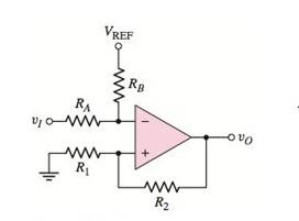
Consider the Schmitt trigger in Figure P15.46. Assume the saturated outputvoltages are
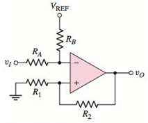
Figure P15.46
(a)
To derive: The expression for the crossover voltage
Answer to Problem 15.46P
The expression for the crossover voltage
Explanation of Solution
Given:
The upper saturated output voltage,
The lowest saturated output voltage,
Calculation:
In an ideal op-amp, the inverting and non-inverting terminal currents are zero. Due to the virtual ground concept, the inverting and non-inverting node voltages are equal.
Given circuit can be represented as
Apply Kirchhoff’s current law at inverting node.
Hence, we get
Apply Kirchhoff’s current law at non-inverting node.
Substitute
When
The upper crossover voltage of Schmitt trigger
Similarly, when
The lower crossover voltage of Schmitt trigger
Conclusion:
Therefore, the expression for the crossover voltage
(b)
To find: the values of
To sketch: The voltage transfer characteristics.
Answer to Problem 15.46P
The required values are
The voltage transfer characteristics are shown in Figure 1
Explanation of Solution
Given:
The circuit voltages are:
Calculation:
The upper crossover voltage is
Therefore, the upper crossover voltage is
The lower crossover voltage is given by,
Therefore, the lower crossover voltage is
The given Schmitt trigger is positive feedback comparator.
Here, the transfer characteristic is a rectangle. Hence, it is called hysteresis which is a dead band. It is so called as the output is not changing
The output remains in the state indefinitely until input voltage crosses the any of the threshold levels.
The voltage transfer characteristics of the given Schmitt trigger is,
Figure 1
Conclusion:
Therefore, the required values are
Therefore, the voltage transfer characteristics are shown in Figure 1.
Want to see more full solutions like this?
Chapter 15 Solutions
Microelectronics: Circuit Analysis and Design


- a) find Rthb) Find Vth in the circuit c)Draw the Thevenin Equivalent of the circuit to tge left of the a and b terminalsarrow_forwardAn electric car runs on batteries, but needs to make constant stops to re-charge. If a trailer is attached to the car that carries a generator, and the generator is turned by a belt attached to the wheels of the trailer, will the car be able to drive forever without stopping?arrow_forwardA singl core cable of voltage 30 kv. The diameter of Conductor is 3 cm. The diameter of cable is 25 cm. This cable has Two layer of insulator having arelative permittivity 5-3 respectively of The ratio of maximum electric stress of maximum electric stress 8 First layer to the of second layer is 10 Find & 1- The thickness of each layers. 3- The voltage of each layers. §. Layers The saving in radius of cable if another ungrading cable has the Same maximum electric stress, Total village, Conductor diameter of grading cable.arrow_forward
- 66 KV sing care Cable has a drameter of conductor of 3 cm. The radius of cable is 10 cm. This Cable house Two relative permmitivity of insulation 6 and 4 respectively. If The ratio of maximum electric stress of first layer to the maximum eledric streep & second layer is s 1- find the village & each layers. 2- Min- electric stress J Cable 3- Compare the voltage of ungrading Cable has the same distance and relectric stresses.arrow_forwardPrelab Information 1. Laboratory Preliminary Discussion First-order Low-pass RC Filter Analysis The first-order low-pass RC filter shown in figure 1 below represents all voltages and currents in the time domain. It is of course possible to solve for all circuit voltages using time domain differential equation techniques, but it is more efficient to convert the circuit to its s-domain equivalent as shown in figure 2 and apply Laplace transform techniques. vs(t) i₁(t) + R₁ ww V₁(t) 12(t) Lic(t) Vout(t) = V2(t) R₂ Vc(t) C Vc(t) VR2(t) = V2(t) + Vs(s) Figure 1: A first-order low-pass RC filter represented in the time domain. I₁(s) R1 W + V₁(s) V₂(s) 12(s) Ic(s) + Vout(S) == Vc(s) Vc(s) Zc(s) = = VR2(S) V2(s) Figure 2: A first-order low-pass RC filter represented in the s-domain.arrow_forwarduse matlabarrow_forward
- I need help with this problem and an explanation of the solution for the image described below. (Introduction to Signals and Systems)arrow_forwardHow do we know that D1 is forward bias and D2 is reverse biased?arrow_forwardSolve it in a different way than the previous solution that I searched forarrow_forward
- A lossless uncharged transmission line of length L = 0.45 cm has a characteristic impedance of 60 ohms. It is driven by an ideal voltage generator producing a pulse of amplitude 10V and width 2 nS. If the transmission line is connected to a load of 200 ohms, sketch the voltage at the load as a function of time for the interval 0 < t < 20 nS. You may assume that the propagation velocity of the transmission is c/2. Answered now answer number 2. Repeat Q.1 but now assume the width of the pulse produced by the generator is 4 nS. Sketch the voltage at the load as a function of time for 0 < t < 20 nS.arrow_forwardSolve this experiment with an accurate solution, please. Thank you.arrow_forwardA lossless uncharged transmission line of characteristic impedance Zo = 600 and length T = 1us is connected to a 180 load. If this transmission line is connected at t = 0 to a 90 V dc source with an internal resistance of 900, from a bounce diagram of this system sketch (a) the voltage at z=0, z=L, and z = L/2 for up to 7.25μs and (b) calculate the load voltage after an infinite amount of time.arrow_forward
 Introductory Circuit Analysis (13th Edition)Electrical EngineeringISBN:9780133923605Author:Robert L. BoylestadPublisher:PEARSON
 Delmar's Standard Textbook Of ElectricityElectrical EngineeringISBN:9781337900348Author:Stephen L. HermanPublisher:Cengage Learning
 Programmable Logic ControllersElectrical EngineeringISBN:9780073373843Author:Frank D. PetruzellaPublisher:McGraw-Hill Education
 Fundamentals of Electric CircuitsElectrical EngineeringISBN:9780078028229Author:Charles K Alexander, Matthew SadikuPublisher:McGraw-Hill Education
 Electric Circuits. (11th Edition)Electrical EngineeringISBN:9780134746968Author:James W. Nilsson, Susan RiedelPublisher:PEARSON
 Engineering ElectromagneticsElectrical EngineeringISBN:9780078028151Author:Hayt, William H. (william Hart), Jr, BUCK, John A.Publisher:Mcgraw-hill Education,