
Videos
(a) Design the circuit shown in Figure P15.72 such that
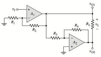
Figure P15.72
Want to see the full answer?
Check out a sample textbook solution
Chapter 15 Solutions
Microelectronics: Circuit Analysis and Design


- For the transistor amplifier shown, R₁-11kQ, R2=6kQ, Rc=2kQ, RE-3kQ and R₁=2k0. (i) Draw d.c. load line (ii) Determine the DC operating point (iii) Draw a.c. load line. Assume V_BE = 0.7 V. and determine the new operating point + Vcc = 15 V RC Cc Cin R1 wwwwww wwwww R₁₂ RE CE RLarrow_forwardthe first part is the second part write your answer such as: (AND, OR, INVERTER, NAND, NOR) D₁ AK D, R₁ B K First Part? the third part is , and the total are R4 R7 Output R5 R₁ T R6 R3 -UBB Second Part? Third Part? Total?arrow_forwardA multistage amplifier has six stages each of which has a power gain of 40. what is the - Total gain of the amplifier in db ? ii- If the negative feedback of 15db is employed, find the resultant gainarrow_forward
- 9.36 Consider the finite-state machine logic implementation in Figure P9.36. (a) Determine the next-state and output logic expressions. (b) Determine the number of possible states. J1 Clk K₁ 101 Ут J2 Clk K₂ Clk Figure P9.36 0 y2 10arrow_forward9.34 Consider the finite-state machine logic implementation in Figure P9.34. (a) Determine the next-state and output logic expressions. (b) Determine the number of possible states. (c) Construct a state assigned table. (d) Construct a state table. (e) Construct a state diagram. (f) Determine the function of the finite-state machine. T₁ x Clk Figure P9.34 Q Clk Q الا T₂ Q 32 Clk Q T3 Q Clk Q Узarrow_forward9.35 Consider the finite-state machine logic implementation in Figure P9.35. (a) Determine the next-state and output logic expressions. (b) Determine the number of possible states. (c) Construct a state assigned table. (d) Construct a state table. (e) Construct a state diagram. (f) Determine the function of the finite-state machine. Clk J Clk K₁ 10 Ут J2 Clk K₂ 10 32 Figure P9.35arrow_forward
- 9.56 Using JK flip-flops, design a synchronous counter that counts in the sequence 1, 3, 0, 2, 1, ... The counter counts only when its enable input x is equal to 1; otherwise, the counter is idle.arrow_forward9.65 Using T flip-flops, design a synchronous counter that counts in the sequence 0, 2, 4, 6, 0, ... The counter counts only when its enable input x is equal to 1; otherwise, the counter is idle.arrow_forward2 Using D flip-flops, design a synchronous counter that counts in the sequence 1, 4, 7, 1, The counter counts only when its enable input x is equal to 1; otherwise, the counter is idle.arrow_forward
- Q1: Write a VHDL code to implement the finite state machine described in the state diagram shown below. Clk D 0 CIK Q D 0 Cik Q =arrow_forwardQ1: Consider the finite state machine logic implementation in Fig. shown below: Construct the state diagram. Repeat the circuit design using j-k flip flop. r" Clk Y D' Y, Clk Q D Clk 10 0 22 3'2arrow_forwardQ: Write a VHDL code to implement the finite state machine described in the state diagram shown below. T 2 Clk Q Clk T₂ 0 la Clk T3 Q Cik 0arrow_forward
 Introductory Circuit Analysis (13th Edition)Electrical EngineeringISBN:9780133923605Author:Robert L. BoylestadPublisher:PEARSON
 Delmar's Standard Textbook Of ElectricityElectrical EngineeringISBN:9781337900348Author:Stephen L. HermanPublisher:Cengage Learning
 Programmable Logic ControllersElectrical EngineeringISBN:9780073373843Author:Frank D. PetruzellaPublisher:McGraw-Hill Education
 Fundamentals of Electric CircuitsElectrical EngineeringISBN:9780078028229Author:Charles K Alexander, Matthew SadikuPublisher:McGraw-Hill Education
 Electric Circuits. (11th Edition)Electrical EngineeringISBN:9780134746968Author:James W. Nilsson, Susan RiedelPublisher:PEARSON
 Engineering ElectromagneticsElectrical EngineeringISBN:9780078028151Author:Hayt, William H. (william Hart), Jr, BUCK, John A.Publisher:Mcgraw-hill Education,