
Concept explainers
Videos
The loop gain, the frequency of the oscillation and the required ratio of the resistance to obtain the oscillation for the given function.
Answer to Problem 15.40P
Explanation of Solution
Given:
The circuit is given as:
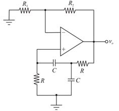
For the ideal operation amplifier, the inverting and non-inverting terminal currents should be 0. The inverting and non inverting node voltages should be equal by the virtual ground concept.
Redrawing the above circuit:
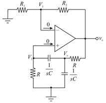
Applying Kirchhoff s current law at node
Hence,
Applying Kirchhoff s current law at non-inverting node:
Substituting
Therefore, the feed-back gain is given as:
Applying Kirchhoff s current law at inverting node:
Therefore,
The loop gain is known as the multiplication of the amplifier gain and the feedback transfer function gain as shown below:
Therefore,
The transfer function is
Put
Therefore,
For frequency oscillation the real part should be 0:
Therefore,
The frequency oscillation is
For the oscillation, the imaginary part is equal to 1:
Therefore,
Want to see more full solutions like this?
Chapter 15 Solutions
Microelectronics: Circuit Analysis and Design


- A domestic load of 2300 kW at 0.88 p.f lagging and a motors load of 3400 kW at 0.85 p.f lagging are supplied by two alternators operating in parallel. If one alternator is delivering a load of 3300 kW at 0.9 p.f lagging, what will be the output power and p.f of the other alternator?arrow_forwardDesign a bank of capacitors to provide 60V and 2kWh energy to capture and store regen breaking energy. Use commercial supercapacitor cells at 3V and 3600F. Capacitor voltage drops almost linearly during discharge and below half voltage maximum it doesn’t provide significant power. If we discharge a fully charged capacitor to its half voltage maximum, how much energy can be discharged compared to a full-discharged capacitor (show your calculation)?arrow_forward8-1) similar to Lathi & Ding, Prob. P.5.1-2 The figure below shows the Fourier spectra of signals of g,(t) and g₁(t). Determine the Nyquist rate and the corresponding sampling interval for signals of g,(t), g,(t), g₁(1) - g¸(1), g¸³(t), and g₁(1)g₁(1). Hint: Use the frequency convolution and the width property of convolution. G₁(f) G₂(f) -8000 0 8000 f -20000 10 20000 farrow_forward
- Calculate the approximate values of the starting current, full-load current, and no- load current of a 150 horsepower, 575 V, 3- phase induction motor.arrow_forwardCapacitor voltage drops almost linearly during discharge and below half voltage maximum it doesn’t provide significant power. If we discharge a fully charged capacitor to its half voltage maximum, how much energy can be discharged compared to a full-discharged capacitor (show your calculation)?arrow_forwardDesign a bank of capacitors to provide 60V and 2kWh energy to capture and store regen breaking energy. Use commercial supercapacitor cells at 3V and 3600F.arrow_forward
- Please explain in step by step detail how to answer and solve this problemarrow_forwardTwo loads connected in parallel are respectively 2 kW at a pf of 0.75 leading and 4 kW at a pf of 0.95 lagging. Calculate the pf of the combined two loads. Find the complex power supplied by the source. Hints: • • Since the two loads are parallel, the complex power, S, supplied by the source is S = S₁+ S₂ Calculate the complex powers, S₁ and S2, of each load (use power triangles) and add them to find the total S. Calculate 0 and obtain pf.arrow_forwardA 3-phase, 20-pole induction motor is con- nected to a 600 V, 60 Hz source. a. What is the synchronous speed? b. If the voltage is reduced to 300 V, will the synchronous speed change? c. How many groups are there, per phase?arrow_forward
- Starting from Maxwell’s equations derive the Kirchohf’s circuit laws for voltage and current. Clearly mention what approximation is used for this derivation.arrow_forwardIn the control system shown in Figure Q4(a), G₁(s) = and G₂(s) == If the system has the specifications for the natural frequency and dampingratio of -5 rad/sec and {=0.7, respectively, determine K and H,(s) when H₂(s) = 1.arrow_forwardCan the expert help me draw a curve on my graph paper? TERMINAL VOLTS 9000 8000 7000 6000 5000 4100 4000 14 18 22 26 30 34 38 FIELD AMPERES, If OPEN CIRCUIT CHARACTERSTICS Fig 3 42 42 46 50 54arrow_forward
 Electricity for Refrigeration, Heating, and Air C...Mechanical EngineeringISBN:9781337399128Author:Russell E. SmithPublisher:Cengage Learning