
(a)
Bias currents
(a)
Answer to Problem 15.16EP
The value of current
The value of current
The reference voltage of temperature compensated portion is 3.08 V
Explanation of Solution
Given:
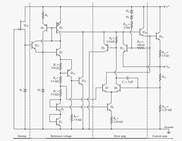
Circuit diagram for voltage regulator is shown below.
The voltage of Zener diode
Transistor parameters of
Also the resistor in the emitter of
The expression for bias current
Substituting 5.6 V for
The value of current
The expression for Emitter-base voltage of transistor
Also,
The expression for emitter-base voltage of transistor
Also,
The expression for emitter-base voltage of transistor
Substituting values of
Substituting value of
Let’s consider the current values 0.205 mA, 0.213 mA, and 0.220 mA for
Substituting values 0.213 mA for
Substituting again 0.220mA for
Hence, the current value 0.213mA is satisfying the equation (2)
After trial and error method it is found that the value of current
The reference voltage of temperature compensated portion (
Substitute 0.6 V for
Hence, the reference voltage of temperature compensated portion is 3.08 V.
(b)
Resistance
(b)
Answer to Problem 15.16EP
The value of resistance
Explanation of Solution
Given:
The voltage of Zener diode
Transistor parameters of
Also the resistor in the emitter of
Given voltage
The expression for reference voltage (
Here,
Let’s re-arrange above expression to find the resistance
Substituting
The value of resistance
Want to see more full solutions like this?
Chapter 15 Solutions
Microelectronics: Circuit Analysis and Design

- A Three-phase, 12 pole, Y-connected alternator has 108 slots and 14 conductors per slot. The windings are (5/6 th) pitched. The flux per pole is 57 mWb distributed sinusoidally over the pole. If the machine runs at 500 r.p.m., determine the following: (a) The frequency of the generated e.m.f., (b) The distribution factor, (c) The pitch factor, and (d) The phase and line values of the generated e.m.f.?arrow_forwardTwo 3-ph, 6.6 kV, Y-connected, alternators supply a load of 3000 kW at 0.8 p.f. lagging. The synchronou impedance per phase of machine A is (0.5+110) and that of machine B is (0.4 +J12) . The excitation of machine A adjusted so that it delivers 150 A. The load is shared equally between the machines. Determine the armature curre p.f., induced e.m.f., and load angle of each machine?arrow_forwardName the circuit below? The output voltage is initially zero and the pulse width is 200 μs. Find the Vout and draw the output waveform? +2.5 V V 247 -2.5 V C 0.01 F Ri W 10 ΚΩarrow_forward
- Please work outarrow_forwardFind Vfinal when Vs up and Vs V. Which LED will light in each case? Red or Green? Justify your answers. Fill the table below. Vs 8 ΚΩ Vos Χρι + 3 ΚΩ www 6 ΚΩ ww 4 ΚΩ Yo www Vo Vec-12 V Nol V final Vm w 3 ΚΩ 5 V 38 ΚΩ R= 1 kQ V -12 V Red LED Green LED Vs Vo Vfinal Which LED is ON? Varrow_forwardCircuits help please solve and explain. Question in images providedarrow_forward
- + V 6.2 A 1.2 A S R 4 Ω Find the source voltage Vs 0.8 Aarrow_forwardDetermine i(t) for t≥ 0 given that the circuit below had been in steady state for a long time prior to t = 0. Also, I₁ = 1 5 A, R₁ =22, R2 =10 Q2, R3 = 32, R4 =7 2, and L=0.15 H. Also fill the table. m L ww R2 t = 0 R₁ 29 R3 R4 Time 0 iL(t) 0 8arrow_forwardPlease help explain this problemarrow_forward
- + P = 16 W w w P = 8 W I R₁ R2 E = RT=322 1- Determine R1, R2, E ΙΩarrow_forward+ 30 V = - 20 V + R 2- Use KVL to find the voltage V - V + + 8 Varrow_forwardFind the Thévenin equivalent circuit for the portions of the networks in Figure external to the elements between points a and b. a R₁ 2002 I = 0.1 A 0° Xc : 32 Ω R2 = 6802 20 Ω фъarrow_forward
 EBK ELECTRICAL WIRING RESIDENTIALElectrical EngineeringISBN:9781337516549Author:SimmonsPublisher:CENGAGE LEARNING - CONSIGNMENT