
Manufacturing Engineering & Technology
7th Edition
ISBN: 9780133128741
Author: Serope Kalpakjian, Steven Schmid
Publisher: Prentice Hall
expand_more
expand_more
format_list_bulleted
Concept explainers
Videos
Textbook Question
Chapter 14, Problem 44SDP
Figure P14.44 shows a round impression-die forging made from a cylindrical blank, as illustrated on the left. As described in this chapter, such parts are made in a sequence of forging operations. Suggest a sequence of intermediate forging steps to make the part on the right, and sketch the shape of the dies needed.
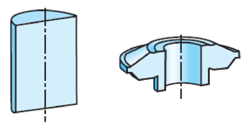
Figure P14.44
Expert Solution & Answer
Want to see the full answer?
Check out a sample textbook solution
Students have asked these similar questions
Qu 5 Determine the carburizing time necessary to achieve a carbon concentration of 0.30 wt% at a position 4 mm into an iron carbon alloy that initially contains 0.10 wt% C. The surface concentration is to be maintained at 0.90 wt% C, and the treatment is to be conducted at 1100°C. Use the data for the diffusion of
carbon into y-iron: Do = 2.3 x10⁻⁵ m2/s and Qd = 148,000 J/mol. Express your answer in hours to three significant figures.
show all work step by step problems formula material science
(Read Question)
In figure A, the homogeneous rod of constant cross section is attached to unyielding supports. In figure B, a homogeneous bar with a cross-sectional area of 600 mm2 is attached to rigid supports. The bar carries the axial loads P1 = 20 kN and P2 = 60 kN, as shown.1. In figure A, derive the expression that calculates the reaction R1 in terms of P, and the given dimensions.2. In figure B, calculate the reaction (kN) at A.3. In figure B, calculate the maximum axial stress (MPa) in the rod.
Chapter 14 Solutions
Manufacturing Engineering & Technology
Ch. 14 - What is the difference between cold, warm, and hot...Ch. 14 - Explain the difference between open-die and...Ch. 14 - Explain the difference between fullering, edging,...Ch. 14 - What is flash? What is its function?Ch. 14 - Why is the intermediate shape of a part important...Ch. 14 - Describe the features of a typical forging die.Ch. 14 - Explain what is meant by load limited, energy...Ch. 14 - What type of parts can be produced by rotary...Ch. 14 - Why is hubbing an attractive alternative to...Ch. 14 - What is the difference between piercing and...
Ch. 14 - What is a hammer? What are the different kinds of...Ch. 14 - Why is there barreling in upsetting?Ch. 14 - What are the advantages and disadvantages of...Ch. 14 - Why are draft angles required in forging dies?Ch. 14 - Is a mandrel needed in swaging?Ch. 14 - Describe and explain the factors that influence...Ch. 14 - How can you tell whether a certain part is forged...Ch. 14 - Identify casting design rules, described in...Ch. 14 - Describe the factors involved in precision...Ch. 14 - Why is control of the volume of the blank...Ch. 14 - Why are there so many types of forging machines...Ch. 14 - What are the advantages and limitations of cogging...Ch. 14 - What are the advantages and limitations of using...Ch. 14 - Review Fig. 14.6e and explain why internal draft...Ch. 14 - Comment on your observations regarding the...Ch. 14 - Describe your observations concerning the control...Ch. 14 - Prob. 27QLPCh. 14 - Describe the difficulties involved in defining the...Ch. 14 - Describe the advantages of servo presses for...Ch. 14 - List the general recommendations you would make...Ch. 14 - Which would you recommend, (a) hot forging and...Ch. 14 - Take two solid, cylindrical specimens of equal...Ch. 14 - Calculate the room-temperature forging force for a...Ch. 14 - Using Eq. (14.2), estimate the forging force for...Ch. 14 - To what thickness can a solid cylinder of 1020...Ch. 14 - In Example 14.1, calculate the forging force,...Ch. 14 - Using Eq. (14.1), make a plot of the forging...Ch. 14 - How would you go about estimating the punch force...Ch. 14 - A mechanical press is powered by a 30-hp motor and...Ch. 14 - A solid cylindrical specimen, made of a perfectly...Ch. 14 - Devise an experimental method whereby you can...Ch. 14 - Assume that you represent the forging industry and...Ch. 14 - Figure P14.44 shows a round impression-die forging...Ch. 14 - Prob. 45SDPCh. 14 - Prob. 46SDPCh. 14 - Review the sequence of operations in the...Ch. 14 - Prob. 48SDPCh. 14 - Discuss the possible environmental concerns...Ch. 14 - List the advantages and disadvantages in using a...
Knowledge Booster


Learn more about
Need a deep-dive on the concept behind this application? Look no further. Learn more about this topic, mechanical-engineering and related others by exploring similar questions and additional content below.Similar questions
- (Read image)arrow_forward(Read Image)arrow_forwardM16x2 grade 8.8 bolts No. 25 C1- Q.2. The figure is a cross section of a grade 25 cast-iron pressure vessel. A total of N, M16x2.0 grade 8.8 bolts are to be used to resist a separating force of 160 kN. (a) Determine ks, km, and C. (b) Find the number of bolts required for a load factor of 2 where the bolts may be reused when the joint 19 mm is taken apart. (c) with the number of bolts obtained in (b), determine the realized load factor for overload, the yielding factor of safety, and the separation factor of safety. 19 mmarrow_forward
- Problem4. The thin uniform disk of mass m = 1-kg and radius R = 0.1m spins about the bent shaft OG with the angular speed w2 = 20 rad/s. At the same time, the shaft rotates about the z-axis with the angular speed 001 = 10 rad/s. The angle between the bent portion of the shaft and the z-axis is ẞ = 35°. The mass of the shaft is negligible compared to the mass of the disk. a. Find the angular momentum of the disk with respect to point G, based on the axis orientation as shown. Include an MVD in your solution. b. Find the angular momentum of the disk with respect to point O, based on the axis orientation as shown. (Note: O is NOT the center of fixed-point rotation.) c. Find the kinetic energy of the assembly. z R R 002 2R x Answer: H = -0.046ĵ-0.040 kg-m²/sec Ho=-0.146-0.015 kg-m²/sec T 0.518 N-m =arrow_forwardProblem 3. The assembly shown consists of a solid sphere of mass m and the uniform slender rod of the same mass, both of which are welded to the shaft. The assembly is rotating with angular velocity w at a particular moment. Find the angular momentum with respect to point O, in terms of the axes shown. Answer: Ñ。 = ½mc²wcosßsinßĵ + (}{mr²w + 2mb²w + ½ mc²wcos²ß) k 3 m r b 2 C لا marrow_forwardOnly question 2arrow_forward
- Only question 1arrow_forwardOnly question 3arrow_forwardI have Euler parameters that describe the orientation of N relative to Q, e = -0.7071*n3, e4 = 0.7071. I have Euler parameters that describe the orientation of U relative to N, e = -1/sqrt(3)*n1, e4 = sqrt(2/3). After using euler parameter rule of successive rotations, I get euler parameters that describe the orientation of U relative to Q, e = -0.4082*n1 - 0.4082*n2 - 0.5774*n3. I need euler parameters that describe the orientation of U relative to Q in vector basis of q instead of n. How do I get that?arrow_forward
- Describe at least 4 processes in engineering where control charts are (or should be) appliedarrow_forwardDescribe at least two (2) processes where control charts are (or should be) applied.arrow_forwardProblem 3: A cube-shaped spacecraft is in a circular Earth orbit. Let N (n,) be inertial and the spacecraft is denoted S (ŝ₁). The spacecraft is described such that ¯½º = J ŝ₁ŝ₁ + J ŝ₂§₂ + J §¸Ŝ3 Location of the spacecraft in the orbit is determined by the orbit-fixed unit vectors ê, that are oriented by the angle (Qt), where is a constant angular rate. 52 €3 3> 2t 55 Λ Из At the instant when Qt = 90°, the spacecraft S is oriented relative to the orbit such that 8₁ = 0° Space-three 1-2-3 angles 0₂ = 60° and ES = $₂ rad/s 0₁ = 135° (a) At this instant, determine the direction cosine matrix that describes the orientation of the spacecraft with respect to the inertial frame N.arrow_forward
arrow_back_ios
SEE MORE QUESTIONS
arrow_forward_ios
Recommended textbooks for you
 Elements Of ElectromagneticsMechanical EngineeringISBN:9780190698614Author:Sadiku, Matthew N. O.Publisher:Oxford University Press
 Mechanics of Materials (10th Edition)Mechanical EngineeringISBN:9780134319650Author:Russell C. HibbelerPublisher:PEARSON
 Thermodynamics: An Engineering ApproachMechanical EngineeringISBN:9781259822674Author:Yunus A. Cengel Dr., Michael A. BolesPublisher:McGraw-Hill Education
 Control Systems EngineeringMechanical EngineeringISBN:9781118170519Author:Norman S. NisePublisher:WILEY
 Mechanics of Materials (MindTap Course List)Mechanical EngineeringISBN:9781337093347Author:Barry J. Goodno, James M. GerePublisher:Cengage Learning
 Engineering Mechanics: StaticsMechanical EngineeringISBN:9781118807330Author:James L. Meriam, L. G. Kraige, J. N. BoltonPublisher:WILEY
Elements Of Electromagnetics
Mechanical Engineering
ISBN:9780190698614
Author:Sadiku, Matthew N. O.
Publisher:Oxford University Press
Mechanics of Materials (10th Edition)
Mechanical Engineering
ISBN:9780134319650
Author:Russell C. Hibbeler
Publisher:PEARSON
Thermodynamics: An Engineering Approach
Mechanical Engineering
ISBN:9781259822674
Author:Yunus A. Cengel Dr., Michael A. Boles
Publisher:McGraw-Hill Education
Control Systems Engineering
Mechanical Engineering
ISBN:9781118170519
Author:Norman S. Nise
Publisher:WILEY
Mechanics of Materials (MindTap Course List)
Mechanical Engineering
ISBN:9781337093347
Author:Barry J. Goodno, James M. Gere
Publisher:Cengage Learning
Engineering Mechanics: Statics
Mechanical Engineering
ISBN:9781118807330
Author:James L. Meriam, L. G. Kraige, J. N. Bolton
Publisher:WILEY
Types of Manufacturing Process | Manufacturing Processes; Author: Magic Marks;https://www.youtube.com/watch?v=koULXptaBTs;License: Standard Youtube License