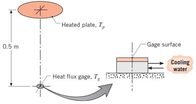
The arrangement shown is to be used to calibrate a heat flux gage. The gage has a black surface that is 10mm in diameter and is maintained at 17°C by means of a water-cooled hacking plate. The heater. 200 mm in diameter, has a black surface that is maintained at 800 K and is located 0.5 m from the gage. The surroundings and the air are at 27°C and the convection heat transfer coefficient between the gage and the air is 15 W/m 2 ⋅ K . (a) Determine the net radiation exchange between the heater and the gage. (b) Determine the net transfer of radiation to the gage per unit area of the gage. (c) What is the net heat transfer rate lo the gage per unit area of the gage? (d) If the gage is constructed according to the description of Problem 3.107, what heat flux will it indicate?
The arrangement shown is to be used to calibrate a heat flux gage. The gage has a black surface that is 10mm in diameter and is maintained at 17°C by means of a water-cooled hacking plate. The heater. 200 mm in diameter, has a black surface that is maintained at 800 K and is located 0.5 m from the gage. The surroundings and the air are at 27°C and the convection heat transfer coefficient between the gage and the air is 15 W/m 2 ⋅ K . (a) Determine the net radiation exchange between the heater and the gage. (b) Determine the net transfer of radiation to the gage per unit area of the gage. (c) What is the net heat transfer rate lo the gage per unit area of the gage? (d) If the gage is constructed according to the description of Problem 3.107, what heat flux will it indicate?
Solution Summary: The author calculates the net radiation exchange between the heater and the gauge.
The arrangement shown is to be used to calibrate a heat flux gage. The gage has a black surface that is 10mm in diameter and is maintained at 17°C by means of a water-cooled hacking plate. The heater. 200 mm in diameter, has a black surface that is maintained at 800 K and is located 0.5 m from the gage. The surroundings and the air are at 27°C and the convection heat transfer coefficient between the gage and the air is
15
W/m
2
⋅
K
.
(a) Determine the net radiation exchange between the heater and the gage. (b) Determine the net transfer of radiation to the gage per unit area of the gage. (c) What is the net heat transfer rate lo the gage per unit area of the gage? (d) If the gage is constructed according to the description of Problem 3.107, what heat flux will it indicate?
For Problems 5–19 through 5–28, design a crank-rocker mechanism with a time ratio of Q, throw angle of (Δθ4)max, and time per cycle of t. Use either the graphical or analytical method. Specify the link lengths L1, L2, L3, L4, and the crank speed.
Q = 1; (Δθ4)max = 78°; t = 1.2s.
a problem existed at the stocking stations of a mini-load AS/RS (automated storage and retrieval system) of a leading electronics manufacturer (Fig.1). At these stations, operators fill the bin delivered by the crane with material arriving in a tote over a roller conveyor. The conveyor was designed at such a height that it was impossible to reach the hooks comfortably even with the tote extended. Furthermore, cost consideration came into the picture and the conveyor height was not reduced. Instead, a step stool was considered to enable the stocker to reach the moving hooks comfortably. The height of the hooks from the floor is 280.2 cm (AD). The tote length is 54.9 cm. The projection of tote length and arm reach, CB = 66.1 cm. a) What anthropometric design principles would you follow to respectively calculate height, length, and width of the step to make it usable to a large number of people? b) What is the minimum height (EF) of the step with no shoe allowance? c) What is the minimum…
Qu. 5 Composite materials are becoming more widely used in aircraft industry due to their high strength, low weight and excellent corrosion resistant properties. As an engineer who is given task to design the I beam section of an aircraft (see Figure 7) please, answer the following questions given the material properties in Table 3.
Determine the Moduli of Elasticity of Carbon/Epoxy, Aramid/Epoxy, and Boron /Epoxy composites in the longitudinal direction, given that the composites consist of 25 vol% epoxy and 75 vol% fiber.
What are the specific moduli of each of these composites?
What are the specific strengths (i.e. specific UTS) of each of these composites?
What is the final cost of each of these composites?please show all work step by step problems make sure to see formula material science
Need a deep-dive on the concept behind this application? Look no further. Learn more about this topic, mechanical-engineering and related others by exploring similar questions and additional content below.


 Principles of Heat Transfer (Activate Learning wi...Mechanical EngineeringISBN:9781305387102Author:Kreith, Frank; Manglik, Raj M.Publisher:Cengage Learning