Videos
Determine F12 and F21 for the following configurations using the reciprocity theorem and other basic shape factor relations. Do not use tables or charts.
- Long duct
(a)
The shape factors.
Answer to Problem 13.1P
The shape factors are 1 and 0.212.
Explanation of Solution
Formula used:
The expression for the shape factor for surface 2 with respect to surface 1 is given as,
Here,
Calculation:
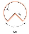
The geometrical shape is given as,
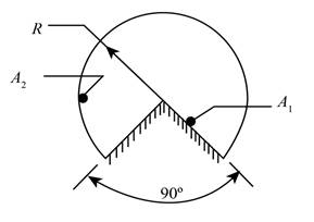
Figure (1)
The above geometry shows that inner surface completely intercepted by the outer surface. Therefore, the value of shape factors can be calculated as,
Conclusion:
Therefore, the shape factors are 1 and 0.212.
(b)
The shape factors.
Answer to Problem 13.1P
The shape factors are 0.5 and 0.25.
Explanation of Solution
Formula used:
The summation rule is given as,
The expression for the shape factor for surface 2 with respect to surface 1 is given as,
Calculation:
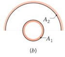
The geometrical shape is given as,
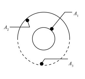
Figure (2)
The above geometry is a convex geometry, therefore the values of shape factor are obtained as,
Further obtaining the values of shape factor by summation rule as,
Further obtaining the values as,
The expression for the shape factor for surface 2 with respect to surface 1 is given as,
Conclusion:
Therefore, the shape factors are 0.5 and 0.25.
(c)
The shape factors.
Answer to Problem 13.1P
The shape factors are 1, 0.637 and 0.363.
Explanation of Solution
Formula used:
The summation rule is given as,
The expression for the shape factor for surface 2 with respect to surface 1 is given as,
The summation rule is given as,
Calculation:
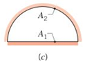
The geometrical shape is given as,
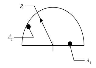
Figure (3)
The above geometry have a flat geometry at bottom, therefore the values of shape factor are obtained as,
Further obtaining the values of shape factor by summation rule as,
The expression for the shape factor for surface 2 with respect to surface 1 can be calculated as,
Further obtain the values of shape factor as,
Conclusion:
Therefore, the shape factors are 1, 0.637 and 0.363
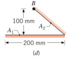
(d)
The shape factors.
Answer to Problem 13.1P
The shape factors are 0.5 and 0.707.
Explanation of Solution
Formula used:
The summation rule is given as,
The expression for the shape factor for surface 2 with respect to surface 1 is given as,
Calculation:
The geometrical shape is given as,
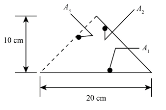
Figure (4)
The above geometry have a flat geometry at bottom, therefore the values of shape factor are obtained as,
Further obtaining the values of shape factor by summation rule as,
The expression for the shape factor for surface 2 with respect to surface 1 can be calculated as,
Conclusion:
Therefore, the shape factors are 0.5 and 0.707.
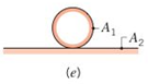
(e)
The shape factors.
Answer to Problem 13.1P
The shape factors are 0.5 and 0.
Explanation of Solution
Formula used:
The summation rule is given as,
The expression for the shape factor for surface 2 with respect to surface 1 is given as,
Calculation:
The geometrical shape is given as,
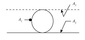
Figure (5)
The above geometry have a flat geometry at bottom, therefore the values of shape factor are obtained as,
Further obtaining the values of shape factor by summation rule as,
The expression for the shape factor for surface 2 with respect to surface 1 can be calculated as,
Conclusion:
Therefore, the shape factors are 0.5 and 0.
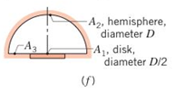
(f)
The shape factors.
Answer to Problem 13.1P
The shape factors are 1 and 0.125.
Explanation of Solution
Formula used:
The summation rule is given as,
The expression for the shape factor for surface 2 with respect to surface 1 is given as,
Calculation:
The geometrical shape is given as,
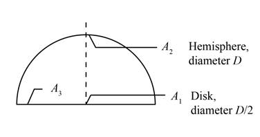
Figure (6)
The above geometry have flat disk surface, therefore the values of shape factor are obtained as,
Further obtaining the values of shape factor by summation rule as,
The expression for the shape factor for surface 2 with respect to surface 1 can be calculated as,
Conclusion:
Therefore, the shape factors are 1 and 0.25.
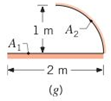
(g)
The shape factors.
Answer to Problem 13.1P
The shape factors are 0.5 and 0.637.
Explanation of Solution
Formula used:
The summation rule is given as,
The expression for the shape factor for surface 2 with respect to surface 1 is given as,
Calculation:
The geometrical shape is given as,
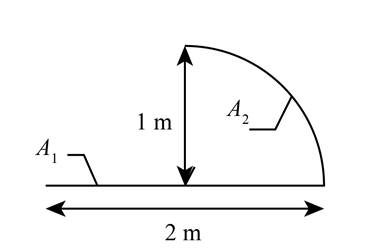
Figure (7)
The above geometry have flat disk surface, therefore the values of shape factor are obtained as,
Further obtaining the values of shape factor by summation rule as,
The expression for the shape factor for surface 2 with respect to surface 1 can be calculated as,
Conclusion:
Therefore, the shape factors are 0.5 and 0.637.
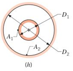
(h)
The shape factors.
Answer to Problem 13.1P
The shape factors are 1 and
Explanation of Solution
Formula used:
The summation rule is given as,
The expression for the shape factor for surface 2 with respect to surface 1 is given as,
Calculation:
The geometrical shape is given as,
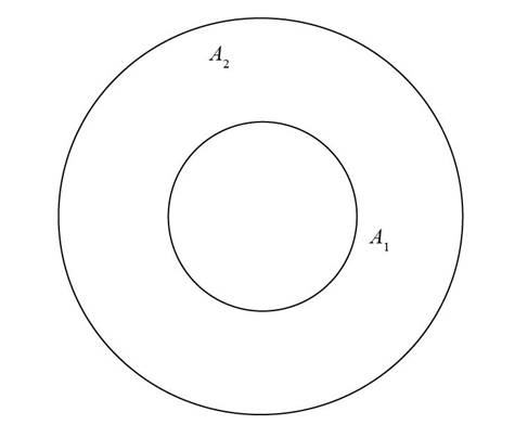
Figure (8)
The above geometry have spherical surface, therefore the values of shape factor are obtained as,
Further obtaining the values of shape factor by summation rule as,
The expression for the shape factor for surface 2 with respect to surface 1 can be calculated as,
Conclusion:
Therefore, the shape factors are 1 and
Want to see more full solutions like this?
Chapter 13 Solutions
Fundamentals of Heat and Mass Transfer
Additional Engineering Textbook Solutions
Vector Mechanics For Engineers
Electric Circuits. (11th Edition)
Thermodynamics: An Engineering Approach
Automotive Technology: Principles, Diagnosis, And Service (6th Edition) (halderman Automotive Series)
Web Development and Design Foundations with HTML5 (8th Edition)
Mechanics of Materials (10th Edition)


- **Problem 8-45.** The man has a mass of 60 kg and the crate has a mass of 100 kg. If the coefficient of static friction between his shoes and the ground is \( \mu_s = 0.4 \) and between the crate and the ground is \( \mu_c = 0.3 \), determine if the man is able to move the crate using the rope-and-pulley system shown. **Diagram Explanation:** The diagram illustrates a scenario where a man is attempting to pull a crate using a rope-and-pulley system. The setup is as follows: - **Crate (C):** Positioned on the ground with a rope attached. - **Rope:** Connects the crate to a pulley system and extends to the man. - **Pulley on Tree:** The rope runs over a pulley mounted on a tree which redirects the rope. - **Angles:** - The rope between the crate and tree forms a \(30^\circ\) angle with the horizontal. - The rope between the tree and the man makes a \(45^\circ\) angle with the horizontal. - **Man (A):** Pulling on the rope with the intention of moving the crate. This arrangement tests the…arrow_forwardplease solve this problems follow what the question are asking to do please show me step by steparrow_forwardplease first write the line action find the forces and them solve the problem step by steparrow_forward
- please solve this problem what the problem are asking to solve please explain step by step and give me the correct answerarrow_forwardplease help me to solve this problem step by steparrow_forwardplease help me to solve this problem and determine the stress for each point i like to be explained step by step with the correct answerarrow_forward
- please solve this problem for me the best way that you can explained to solve please show me the step how to solvearrow_forwardplese solbe this problem and give the correct answer solve step by step find the forces and line actionarrow_forwardplease help me to solve this problems first write the line of action and them find the forces {fx=0: fy=0: mz=0: and them draw the shear and bending moment diagram. please explain step by steparrow_forward
- please solve this problem step by step like human and give correct answer step by steparrow_forwardPROBLEM 11: Determine the force, P, that must be exerted on the handles of the bolt cutter. (A) 7.5 N (B) 30.0 N (C) 52.5 N (D) 300 N (E) 325 N .B X 3 cm E 40 cm cm F = 1000 N 10 cm 3 cm boltarrow_forwardUsing the moment-area theorems, determine a) the rotation at A, b) the deflection at L/2, c) the deflection at L/4. (Hint: Use symmetry for Part a (θA= - θB, or θC=0), Use the rotation at A for Parts b and c. Note that all deformations in the scope of our topics are small deformation and for small θ, sinθ=θ).arrow_forward
 International Edition---engineering Mechanics: St...Mechanical EngineeringISBN:9781305501607Author:Andrew Pytel And Jaan KiusalaasPublisher:CENGAGE L