A long rod heater of diameter D 1 = 10 mm and emissivity ε 1 = 1.0 is coaxial with a well-insulated, semi-cylindrical reflector of diameter D 2 = 1 m . A long panel of width W = 1 m is aligned with the reflector and is separated from the healer by a distance of H = 1 m . The panel is coaled with a special paint ( ε 3 = 0.7 ) , which is cured by maintaining it at 400 K. The panel is well insulated on its back side, and the entire system is located in a large room where the walls and the atmospheric, quiescent air are at 300 K. Heat transfer by convection may be neglected for the reflector surface. (a) Sketch the equivalent thermal circuit for the system and label all pertinent resistances and potentials. (b) Expressing your results in terms of appropriate variables, write the system of equations needed to determine the heater and reflector temperatures, T 1 and T 2 , respectively. Determine these temperatures for the prescribed conditions. (c) Determine the rate at which electrical power must be supplied per unit length of the rod heater.
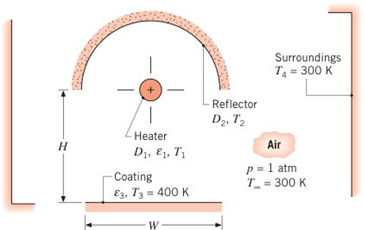
A long rod heater of diameter D 1 = 10 mm and emissivity ε 1 = 1.0 is coaxial with a well-insulated, semi-cylindrical reflector of diameter D 2 = 1 m . A long panel of width W = 1 m is aligned with the reflector and is separated from the healer by a distance of H = 1 m . The panel is coaled with a special paint ( ε 3 = 0.7 ) , which is cured by maintaining it at 400 K. The panel is well insulated on its back side, and the entire system is located in a large room where the walls and the atmospheric, quiescent air are at 300 K. Heat transfer by convection may be neglected for the reflector surface. (a) Sketch the equivalent thermal circuit for the system and label all pertinent resistances and potentials. (b) Expressing your results in terms of appropriate variables, write the system of equations needed to determine the heater and reflector temperatures, T 1 and T 2 , respectively. Determine these temperatures for the prescribed conditions. (c) Determine the rate at which electrical power must be supplied per unit length of the rod heater.
Solution Summary: The author explains the equivalent thermal circuit for the system with all pertinent resistances and potentials.
A long rod heater of diameter
D
1
=
10
mm
and emissivity
ε
1
=
1.0
is coaxial with a well-insulated, semi-cylindrical reflector of diameter
D
2
=
1
m
. A long panel of width
W
=
1
m
is aligned with the reflector and is separated from the healer by a distance of
H
=
1
m
. The panel is coaled with a special paint
(
ε
3
=
0.7
)
, which is cured by maintaining it at 400 K. The panel is well insulated on its back side, and the entire system is located in a large room where the walls and the atmospheric, quiescent air are at 300 K. Heat transfer by convection may be neglected for the reflector surface. (a) Sketch the equivalent thermal circuit for the system and label all pertinent resistances and potentials. (b) Expressing your results in terms of appropriate variables, write the system of equations needed to determine the heater and reflector temperatures, T1and T2, respectively. Determine these temperatures for the prescribed conditions. (c) Determine the rate at which electrical power must be supplied per unit length of the rod heater.
Quick solution required.
My request, Don't use Ai.
Mechanical engineering
Please give handwritten solution, don't use chatgpt.
Fbd should be included
(I) [40 Points] Using centered finite difference approximations as done in class, solve the equation for O:
d20
dx²
+ 0.010+ Q=0
subject to the boundary conditions shown in the stencil below. Do this for two values of Q: (a) Q = 0.3,
and (b) Q= √(0.5 + 2x)e-sinx (cos(5x)+x-0.5√1.006-x| + e −43*|1+.001+x* | * sin (1.5 − x) +
(cosx+0.001 + ex-1250+ sin (1-0.9x)|) * x - 4.68x4. For Case (a) (that is, Q = 0.3), use the stencil in Fig.
1. For Case (b), calculate with both the stencils in Fig. 1 and Fig 2. For all the three cases, show a table as
well as a plot of O versus x. Discuss your results. Use MATLAB and hand in the MATLAB codes.
1
0=0
x=0
2
3
4
0=1
x=1
Fig 1
1 2 3 4 5 6 7 8 9 10
11
0=0
x=0
0=1
x=1
Fig 2
Need a deep-dive on the concept behind this application? Look no further. Learn more about this topic, mechanical-engineering and related others by exploring similar questions and additional content below.


 Principles of Heat Transfer (Activate Learning wi...Mechanical EngineeringISBN:9781305387102Author:Kreith, Frank; Manglik, Raj M.Publisher:Cengage Learning