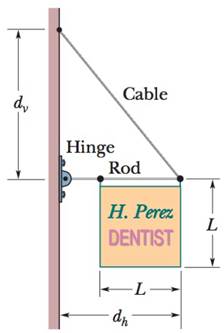
GO In Fig. 12-46, a 50.0 kg uniform square sign, of edge length L = 2.00 m, is hung from a horizontal rod of length d h = 3.00 m and negligible mass. A cable is attached to the end of the rod and to a point on the wall at distance d v = 4.00 m above the point where the rod is hinged to the wall. (a) What is the tension in the cable? What are the (b) magnitude and (c) direction (left or right) of the horizontal component of the force on the rod from the wall, and the (d) magnitude and (e) direction (up or down) of the vertical component of this force? Figure 12-46 Problem 30.
GO In Fig. 12-46, a 50.0 kg uniform square sign, of edge length L = 2.00 m, is hung from a horizontal rod of length d h = 3.00 m and negligible mass. A cable is attached to the end of the rod and to a point on the wall at distance d v = 4.00 m above the point where the rod is hinged to the wall. (a) What is the tension in the cable? What are the (b) magnitude and (c) direction (left or right) of the horizontal component of the force on the rod from the wall, and the (d) magnitude and (e) direction (up or down) of the vertical component of this force? Figure 12-46 Problem 30.
GO In Fig. 12-46, a 50.0 kg uniform square sign, of edge length L = 2.00 m, is hung from a horizontal rod of length dh = 3.00 m and negligible mass. A cable is attached to the end of the rod and to a point on the wall at distance dv = 4.00 m above the point where the rod is hinged to the wall. (a) What is the tension in the cable? What are the (b) magnitude and (c) direction (left or right) of the horizontal component of the force on the rod from the wall, and the (d) magnitude and (e) direction (up or down) of the vertical component of this force?
For each of the actions depicted below, a magnet and/or metal loop moves with velocity v→ (v→ is constant and has the same magnitude in all parts). Determine whether a current is induced in the metal loop. If so, indicate the direction of the current in the loop, either clockwise or counterclockwise when seen from the right of the loop. The axis of the magnet is lined up with the center of the loop. For the action depicted in (Figure 5), indicate the direction of the induced current in the loop (clockwise, counterclockwise or zero, when seen from the right of the loop). I know that the current is clockwise, I just dont understand why. Please fully explain why it's clockwise, Thank you
A planar double pendulum consists of two point masses \[m_1 = 1.00~\mathrm{kg}, \qquad m_2 = 1.00~\mathrm{kg}\]connected by massless, rigid rods of lengths \[L_1 = 1.00~\mathrm{m}, \qquad L_2 = 1.20~\mathrm{m}.\]The upper rod is hinged to a fixed pivot; gravity acts vertically downward with\[g = 9.81~\mathrm{m\,s^{-2}}.\]Define the generalized coordinates \(\theta_1,\theta_2\) as the angles each rod makes with thedownward vertical (positive anticlockwise, measured in radians unless stated otherwise).At \(t=0\) the system is released from rest with \[\theta_1(0)=120^{\circ}, \qquad\theta_2(0)=-10^{\circ}, \qquad\dot{\theta}_1(0)=\dot{\theta}_2(0)=0 .\]Using the exact nonlinear equations of motion (no small-angle or planar-pendulumapproximations) and assuming the rods never stretch or slip, determine the angle\(\theta_2\) at the instant\[t = 10.0~\mathrm{s}.\]Give the result in degrees, in the interval \((-180^{\circ},180^{\circ}]\).
What are the expected readings of the ammeter and voltmeter for the circuit in the figure below? (R = 5.60 Ω, ΔV = 6.30 V)
ammeter
I =
Fundamentals of Anatomy & Physiology (11th Edition)
Knowledge Booster
Learn more about
Need a deep-dive on the concept behind this application? Look no further. Learn more about this topic, physics and related others by exploring similar questions and additional content below.


 Physics for Scientists and Engineers: Foundations...PhysicsISBN:9781133939146Author:Katz, Debora M.Publisher:Cengage Learning
 University Physics Volume 1PhysicsISBN:9781938168277Author:William Moebs, Samuel J. Ling, Jeff SannyPublisher:OpenStax - Rice University
 Principles of Physics: A Calculus-Based TextPhysicsISBN:9781133104261Author:Raymond A. Serway, John W. JewettPublisher:Cengage Learning
 Physics for Scientists and EngineersPhysicsISBN:9781337553278Author:Raymond A. Serway, John W. JewettPublisher:Cengage Learning
 Physics for Scientists and Engineers with Modern ...PhysicsISBN:9781337553292Author:Raymond A. Serway, John W. JewettPublisher:Cengage Learning
 College PhysicsPhysicsISBN:9781285737027Author:Raymond A. Serway, Chris VuillePublisher:Cengage Learning