Principles of Foundation Engineering (MindTap Course List)
9th Edition
ISBN: 9781337705028
Author: Braja M. Das, Nagaratnam Sivakugan
Publisher: Cengage Learning
expand_more
expand_more
format_list_bulleted
Textbook Question
Chapter 12, Problem 12.7P
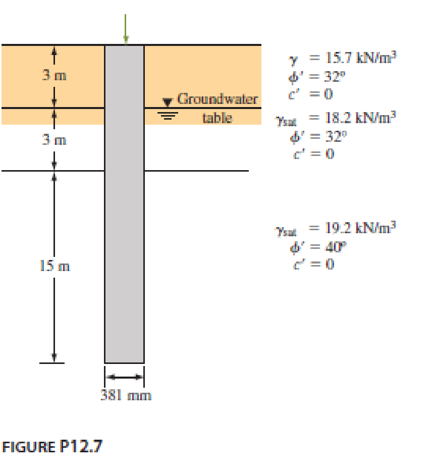
A driven closed-ended pile, circular in cross section, is shown in Figure P12.7. Calculate the following.
- a. The ultimate point load using Meyerhof’s procedure.
- b. The ultimate point load using Vesic’s procedure. Take Irr = 50.
- c. An approximate ultimate point load on the basis of parts (a) and (b).
- d. The ultimate frictional resistance Qs. [Use Eqs. (12.42) through (12.44), and take K = 1.4 and δ′ = 0.6ϕ′.]
- e. The allowable load of the pile (use FS = 4).

Expert Solution & Answer
Trending nowThis is a popular solution!

Students have asked these similar questions
SOLVE BY NEWTON - RAPHSON METHOD:
The equation x³-3x-4=0 is of the form f(x) = 0 where f(1) 0 so there is a solution to the equation between 1 and 3. We
shall take this to be 2, by bisection. Find a better approximation to
the root.
Kindly help to provide answers, elaborate with examples and provide useful links for learning purposes.
this is regarding building diagnosis.
pounds of steel need to be purchased for the roof plan
a table with various steel types and the quantity needed
The colums are 18 feet high and weigh 76 ponds per foot
include a structural steel material list for the roof framing plan
Chapter 12 Solutions
Principles of Foundation Engineering (MindTap Course List)
Ch. 12 - Prob. 12.1PCh. 12 - A 20 m long concrete pile is shown in Figure...Ch. 12 - A 500 mm diameter are 20 m long concrete pile is...Ch. 12 - Redo Problem 12.3 using Coyle and Castellos...Ch. 12 - A 400 mm 400 mm square precast concrete pile of...Ch. 12 - Determine the maximum load that can be allowed on...Ch. 12 - A driven closed-ended pile, circular in cross...Ch. 12 - Consider a 500 mm diameter pile having a length of...Ch. 12 - Determine the maximum load that can be allowed on...Ch. 12 - Prob. 12.10P
Ch. 12 - Prob. 12.11PCh. 12 - Prob. 12.12PCh. 12 - A concrete pile 16 in. 16 in. in cross section is...Ch. 12 - Prob. 12.14PCh. 12 - Solve Problem 12.13 using Eqs. (12.59) and...Ch. 12 - Prob. 12.16PCh. 12 - Prob. 12.17PCh. 12 - A steel pile (H-section; HP 310 125; see Table...Ch. 12 - Prob. 12.19PCh. 12 - A 600 mm diameter and 25 m long driven concrete...Ch. 12 - Redo Problem 12.20 using Vesics method, assuming...Ch. 12 - Prob. 12.22PCh. 12 - Prob. 12.23PCh. 12 - Solve Problem 12.23 using the method of Broms....Ch. 12 - Prob. 12.25PCh. 12 - Solve Problem 12.25 using the modified EN formula....Ch. 12 - Solve Problem 12.25 using the modified Danish...Ch. 12 - Prob. 12.28PCh. 12 - Prob. 12.29PCh. 12 - Figure 12.49a shows a pile. Let L = 15 m, D (pile...Ch. 12 - Redo Problem 12.30 assuming that the water table...Ch. 12 - Refer to Figure 12.49b. Let L = 18 m, fill = 17...Ch. 12 - Estimate the group efficiency of a 4 6 pile...Ch. 12 - The plan of a group pile is shown in Figure...Ch. 12 - Prob. 12.35PCh. 12 - Figure P12.36 shows a 3 5 pile group consisting...Ch. 12 - Prob. 12.37P
Knowledge Booster
Learn more about
Need a deep-dive on the concept behind this application? Look no further. Learn more about this topic, civil-engineering and related others by exploring similar questions and additional content below.Similar questions
- Homework: Determine the proportions of the separate aggregates that will give a gradation within the SCRB wearing coarse specified limits for the aggregates and mix composition for highway pavement asphaltic concrete. The table below shows the results of sieve analysis of samples from the materials available. برو Percent by Weight Passing Sieve Designation Retained on Sieve Designation Coarse Aggregate Fine Aggregate Mineral Filler 3/4 in. (19 mm) 1/2 in. 5 ½ in. (12.5 mm) 3/8 in. 35 ¾ in. (9.5 mm) No. 4 38 No. 4 (4.75 mm) No. 10 17 No. 10 (2 mm) No. 40 5 No. 40 (0.425 mm) No. 80 No. 80 (0.180 mm) No. 200 No. 200 (0.075 mm) Total 18 1118 30 35 5 26 35 60 100 100 100arrow_forwardFor the driven pile shown in figure, estimate the allowable capacity by: (a) Tomlinson a-method, (b)Vijayvergia and Focht A-method. Which one of the two methods are more conservative? Qall =? W.T 18.21 kN/m² 930 L=18m Square pile 27.5cm x 27.5cmarrow_forwardWhat is the vertical deflection at joint C of the truss shown? 75 kN 9 m 7 (3000 mm²) (3000 mm²) (2000 mm²) (3000 mm²) (2000 mm²) 100 kN (3000 mm²) H (3000 mm²) (2000 mm²) (2000 mm²) (3000 mm²)B(3000 mm²) C(3000 mm²)D(3000 mm2)5 a. 9.3 mm↓ b. 9.6 mm↓ c. 8.0 mm ↓ d. 9.1 mm↓ 4 at 6 m = 24 m E = 200 GPa Earrow_forward
- INVERSE FROM POINT A TOWARDS POINT B GIVEN THE FOLLOWINGCOORDINATE VALUES: POINT AN=13,163,953.37'E=3,072,227.10' POINT BN=13,163,463.03'E=3,072,129.30' FIND THE FOLLOWING:DISTANCE FROM A TO BNORTH AZIMUTH (NAZ) FROM A TOWARDS BBEARING OF THE LINE FROM A TOWARDS Barrow_forwardFORWARD FROM POINT B TO POINT A GIVEN THE FOLLOWING: POINT BN=13,163,463.03'E=3,072,129.30' DIRECTION FROM B TO A (NAZ)=276.07529° DISTANCE FROM B TO A = 10.00'arrow_forwardA cheetah is crouched 20 m to the east of an observer. At time t = 0 s, the cheetah begins to run due east toward an antelope that is 50 m to the east of the observer. During the first 2.0 s of the attack, the cheetah's coordinate x varies with time according to the equation x = 20 + 5t?. (a) Find the cheetah's displacement between t1 = 1.0 s and t2 = 2.0 s. (b) Find its average velocity during that interval. (c) Derive an expression for the cheetah's instantaneous velocity as a function of time, and use it to find Vy at t = 1.0 s and t = 2.0 s.arrow_forward
- Write at least 20 words for vocabulary and 10 verbs .for simple present, past, and past participlesarrow_forwardCan you compute the Panel Board Management while using the Lighting and Power Layout Plan as the base for it? The attached Panel Board Management picture is just an example. ps. not graded, I just want to know how to compute it based on a planarrow_forwardMake Sure the attached pic is correct, because the answer in mannings equation is wrong. Can you design a (Open Channel): -Most Efficient Section (Rectangular Shape) -Cost Estimate -Structural Analysis Design Requirements: Bed Slope= 1:1500 Manning's (n)= 0.015 Discharge: Q= 18 m^3/sarrow_forward
- 2-7 The force P applied at joint D of the square frame causes the frame to sway and form the dashed rhombus. Determine the average normal strain developed in wire AC. Assume the three rods are rigid. I understand how you calculate length LAC its just the sqrt(400^2+400^2) = 565.685mm. I do understand that you have to take LAC'-LAC/LAC to get .0258mm/mm. I'm just not understanding the cosine law used to calculate LAC'. I guess what I'm asking is why do you use cos instead of sin or tangent? I've been trying to understand why that was used for a bit now and it's probably something simple I'm forgetting. If you can, please clarify it in detail. Thank you so much!arrow_forwardTraffic flow on a three-lane (one direction) freeway can be described by the Greenshields model. One lane of the three lanes on a section of this freeway will have to be closed to undertake an emergency bridge repair that is expected to take 2 hours. It is estimated that the capacity at the work zone will be reduced by 30 percent of that of the section just upstream of the work zone. The mean free flow speed of the highway is 70 mi/h and the jam density is 150 veh/mi/In. If it is estimated that the demand flow on the highway during the emergency repairs is 85 percent of the capacity, using the deterministic approach, determine the following. (a) the maximum queue length (in veh) that will be formed veh (b) the total delay (in h) h (c) the number of vehicles that will be affected by the incident veh (d) the average individual delay (in min) minarrow_forwardNon-constant sections are used in bridges without changing the appearance of the bridge significantly. Refer to the figure below. Compute the ratio of moment inertial after to before of the plate girder shown (greater than 1). A 10x0.5" steel plate of the same grade as the plate girder and is fillet welded to the flangesarrow_forward
arrow_back_ios
SEE MORE QUESTIONS
arrow_forward_ios
Recommended textbooks for you
 Principles of Foundation Engineering (MindTap Cou...Civil EngineeringISBN:9781337705028Author:Braja M. Das, Nagaratnam SivakuganPublisher:Cengage Learning
 Fundamentals of Geotechnical Engineering (MindTap...Civil EngineeringISBN:9781305635180Author:Braja M. Das, Nagaratnam SivakuganPublisher:Cengage Learning
 Principles of Foundation Engineering (MindTap Cou...Civil EngineeringISBN:9781305081550Author:Braja M. DasPublisher:Cengage Learning
 Principles of Geotechnical Engineering (MindTap C...Civil EngineeringISBN:9781305970939Author:Braja M. Das, Khaled SobhanPublisher:Cengage Learning

Principles of Foundation Engineering (MindTap Cou...
Civil Engineering
ISBN:9781337705028
Author:Braja M. Das, Nagaratnam Sivakugan
Publisher:Cengage Learning

Fundamentals of Geotechnical Engineering (MindTap...
Civil Engineering
ISBN:9781305635180
Author:Braja M. Das, Nagaratnam Sivakugan
Publisher:Cengage Learning

Principles of Foundation Engineering (MindTap Cou...
Civil Engineering
ISBN:9781305081550
Author:Braja M. Das
Publisher:Cengage Learning

Principles of Geotechnical Engineering (MindTap C...
Civil Engineering
ISBN:9781305970939
Author:Braja M. Das, Khaled Sobhan
Publisher:Cengage Learning
Concrete Slab Calculations 006; Author: Jerry Howard;https://www.youtube.com/watch?v=R19jILyBxio;License: Standard Youtube License