
Principles of Foundation Engineering (MindTap Course List)
9th Edition
ISBN: 9781337705028
Author: Braja M. Das, Nagaratnam Sivakugan
Publisher: Cengage Learning
expand_more
expand_more
format_list_bulleted
Concept explainers
Videos
Textbook Question
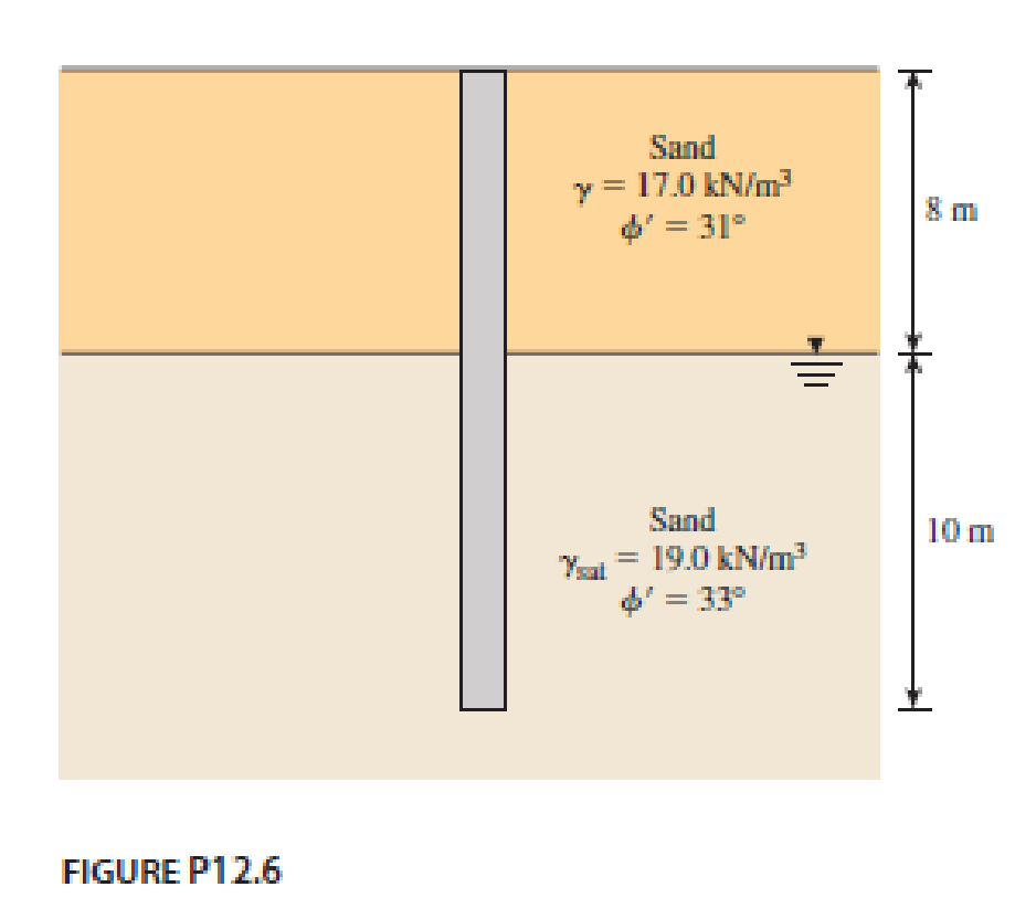
Chapter 12, Problem 12.6P
Determine the maximum load that can be allowed on a 450 mm diameter driven pile shown in Figure P12.6, allowing a factor of safety of 3. Use K = 1.5 Ko and δ′ = 0.65ϕ′ in computing the shaft load. Use Meyerhof’s method for computing the point load.
Expert Solution & Answer

Trending nowThis is a popular solution!

Students have asked these similar questions
+
54
7h
de
зк
+F
8
B
8
Ө
6
For Primary Structure remove
and cut BF
For redundant structures
Redundant
"
"
2
склес
しん
Ik @D
3 14 @ BF
しん
↑
A=Sin² E=290ooks for
diagonal members
A= 30.25in² E = 1800 ksi
for hoizontal &
Vertical members
roller@G, make Da roller
An urban freeway is to be designed using the following information.
AADT = 52,600 veh/day
K (proportion of AADT occurring during the peak hour):
D (proportion of peak hour traffic traveling in the peak direction):
Trucks:
0.11
0.65
8% of peak hour volume
PHF = 0.94
Lane width:
Shoulder width:
Total ramp density:
Terrain:
12 ft
10 ft
0.5 interchange/mile; all interchanges are to be cloverleaf interchanges
rolling
Determine the number of lanes in the peak direction required to provide LOS C. (Assume commuter traffic and assume no RVs.)
lanes
Show all calculations required. (Calculate your answers for the peak direction only. Enter fy the peak hour volume in veh/h, the free flow speed in mi/h, the demand flow rate in pc/h/In, the mean speed in mi/h, and the density in pc/mi/In.)
fHV
peak hour volume
free flow speed
demand flow rate
mean speed
veh/h
mi/h
pc/h/In
mi/h
density
pc/mi/In
The beam shown in the figure below is a W16 × 31 of A992 steel and has continuous lateral support. The two concentrated loads are service live
loads. Neglect the weight of the beam and determine whether the beam is adequate. Suppose that P = 56 k.
For W16 x 31: d=15.9 in., t = 0.275 in., h/t = 51.6,
and M = M₁ = 203 ft-kip, M/
P
P
=
= Mp/
=135 ft-kip.
6'
W16 x 31
a. Use LRFD.
Calculate the required moment strength, the allowable shear strength, and the maximum shear.
(Express your answers to three significant figures.)
=
Mu
QvVn
Vu
=
=
Beam is -Select-
b. Use ASD.
ft-kip
kips
kips
Calculate the required moment strength, the allowable shear strength, and the maximum shear.
(Express your answers to three significant figures.)
Ma
=
Vn/b
Va
=
=
Beam is -Select-
ft-kip
kips
kips
Chapter 12 Solutions
Principles of Foundation Engineering (MindTap Course List)
Ch. 12 - Prob. 12.1PCh. 12 - A 20 m long concrete pile is shown in Figure...Ch. 12 - A 500 mm diameter are 20 m long concrete pile is...Ch. 12 - Redo Problem 12.3 using Coyle and Castellos...Ch. 12 - A 400 mm 400 mm square precast concrete pile of...Ch. 12 - Determine the maximum load that can be allowed on...Ch. 12 - A driven closed-ended pile, circular in cross...Ch. 12 - Consider a 500 mm diameter pile having a length of...Ch. 12 - Determine the maximum load that can be allowed on...Ch. 12 - Prob. 12.10P
Ch. 12 - Prob. 12.11PCh. 12 - Prob. 12.12PCh. 12 - A concrete pile 16 in. 16 in. in cross section is...Ch. 12 - Prob. 12.14PCh. 12 - Solve Problem 12.13 using Eqs. (12.59) and...Ch. 12 - Prob. 12.16PCh. 12 - Prob. 12.17PCh. 12 - A steel pile (H-section; HP 310 125; see Table...Ch. 12 - Prob. 12.19PCh. 12 - A 600 mm diameter and 25 m long driven concrete...Ch. 12 - Redo Problem 12.20 using Vesics method, assuming...Ch. 12 - Prob. 12.22PCh. 12 - Prob. 12.23PCh. 12 - Solve Problem 12.23 using the method of Broms....Ch. 12 - Prob. 12.25PCh. 12 - Solve Problem 12.25 using the modified EN formula....Ch. 12 - Solve Problem 12.25 using the modified Danish...Ch. 12 - Prob. 12.28PCh. 12 - Prob. 12.29PCh. 12 - Figure 12.49a shows a pile. Let L = 15 m, D (pile...Ch. 12 - Redo Problem 12.30 assuming that the water table...Ch. 12 - Refer to Figure 12.49b. Let L = 18 m, fill = 17...Ch. 12 - Estimate the group efficiency of a 4 6 pile...Ch. 12 - The plan of a group pile is shown in Figure...Ch. 12 - Prob. 12.35PCh. 12 - Figure P12.36 shows a 3 5 pile group consisting...Ch. 12 - Prob. 12.37P
Knowledge Booster


Learn more about
Need a deep-dive on the concept behind this application? Look no further. Learn more about this topic, civil-engineering and related others by exploring similar questions and additional content below.Similar questions
- ***Please answer all parts. They are part of a single question and not different questions altogether. I will like the solution as well. Thank you!arrow_forwardConsider the geometric and traffic characteristics shown below. Approach (Width) Peak hour Approach Volumes: Left Turn Through Movement Right Turn Conflicting Pedestrian Volumes PHF For the following saturation flows: North (56 ft) South (56 ft) East (68 ft) West (68 ft) 165 105 200 166 442 395 585 538 162 157 191 200 900 1,200 1,200 900 0.95 0.95 0.95 0.95 Through lanes: 1,600 veh/h/in Through-right lanes: 1,400 veh/h/in Left lanes: 1,000 veh/h/in Left-through lanes: 1,200 veh/h/in Left-through-right lanes: 1,100 veh/h/in The total cycle length was 277 s. Now assume the saturation flow rates are 10% higher, that is, assume the following saturation flow rates: Through lanes: Through-right lanes: Left lanes: Left-through lanes: Left-through-right lanes: 1,760 veh/h/in 1,540 veh/h/in 1,100 veh/h/in 1,320 veh/h/in 1,210 veh/h/in Determine a suitable signal phasing system and phase lengths (in s) for the intersection using the Webster method. (Enter the sum of green and yellow times for…arrow_forwardDetermine the minimum of the appropriate yellow interval (Y . approach speed limit: 45 mi/h approach grade: 3.2% downgrade assumed perception-reaction time: 1.0 sec assumed deceleration rate: 11.2 ft/sec² assumed average vehicle length: 20 ft width of intersection to be crossed: 56 ft min' in s) for a signal phase under the following conditions.arrow_forward
- Compute the nominal shear strength of an M10 × 7.5 of A572 Grade 60 steel (Fy = 60 ksi). For M10 × 7.5: d = 9.99 in., tw = 0.13 in., h/tw Vn = x kips = 71.arrow_forwardA flexural member is fabricated from two flange plates 1/2 × 71/2 and a web plate 3/8 × 20. The yield stress of the steel is 50 ksi. a. Compute the plastic section modulus Z and the plastic moment Mp with respect to the major principal axis. (Express your answers to three significant figures.) Z = Mp = in. 3 ft-kips b. Compute the elastic section modulus S and the yield moment My with respect to the major principal axis. (Express your answers to three significant figures.) S = My = in.3 ft-kipsarrow_forwardThe beam shown in the figure below has lateral support at the ends only. The concentrated loads are live loads. Use A992 steel and select a shape. Do not check deflections. Use C = 1.0 (this is conservative). Suppose that PL = 20 k. PL PL Use the table below. Shape Mn Mn Vn Vn Ω Ων W12 × 58 216 144 132 87.8 W12 × 65 269 179 142 94.4 W12 × 72 308 205 159 106 W14 × 61 235 157 156 104 W14 × 68 280 187 174 116 W14 × 74 318 212 192 128 W16 × 67 276 184 193 129 18' a. Use LRFD. Calculate the factored-load moment (not including the beam weight). (Express your answer to three significant figures.) Mu = ft-kips Select a shape. -Select- b. Use ASD. Calculate the required flexural strength (not including the beam weight). (Express your answer to three significant figures.) Ma = Select a shape. -Select- ft-kipsarrow_forward
- Given a portion of a pipe network below. Determine the true discharge in each pipe using the Hardy-Cross method. Use the Darcy-Weisbach formula with f = 0.02 for all pipes.arrow_forwardFor the cantilever retaining wall shown in the figure below, let the following data be given: Wall dimensions: H = 6.5 m, x1 = 0.3 m, x2 = 0.6 m, x3 = 0.8 m, x4 =2m, x5 = 0.8 m, D= 1.5 m, a = 0° Soil properties: 1 = 17.58 kN/m³, 1 = 36°, Y2 = 19.65 kN/m³, 215°, c230 kN/m² For 2=15°: Ne 10.98; N₁ = 3.94; N₁ = = 2.65. H Calculate the factor of safety with respect to overturning, sliding, and bearing capacity. Use Y concrete = 24.58 kN/m³. Also, use k₁ = k₂ = 2/3 and Pp FS (sliding) (EV) tan(k102) + Bk2c₂ + Pp Pa cos a (Enter your answers to three significant figures.) = 0 in equation FS (overturning)= FS(sliding)= FS(bearing)arrow_forwardA W16×67 of A992 steel has two holes in each flange for 7/8-inch-diameter bolts. For A992 steel: Fy = 50 ksi, F₁ = 65 ksi. For a W16×67: bƒ = 10.2 in., tf = 0.665 in., Zx =130 in.3 and S = 117 in.3 a. Assuming continuous lateral support, verify that the holes must be accounted for and determine the nominal flexural strength. (Express your answer to three significant figures.) Mn = ft-kips b. What is the percent reduction in strength? (Express your answer to three significant figures.) % Reduction =arrow_forward
- A gravity retaining wall is shown in the figure below. Calculate the factor of safety with respect to overturning and sliding, given the following data: Wall dimensions: H = 6 m, x1 = 0.6 m, x2 = 2 m, x3 = 2m, x4 = 0.5 m, x5 = 0.75 m, x6 = 0.8 m, D= 1.5 m Soil properties: 1 = 17.5 kN/m³, ø₁ = 32°, 12 = 18 kN/m³, =22°, 40 kN/m² Y₁ H D x2 x3 x5 X6 Use the Rankine active earth pressure in your calculation. Use Yconcrete = 23.58 kN/m³. Also, use k₁ = k₂ = 2/3 and P₁ = 0 in the equation FS S(sliding) | tan(k102) + Bk₂c½ + Pp (Σν). Pa cos a (Enter your answers to three significant figures.) FS (overturning) FS (sliding)arrow_forwardQ4 Use b member Castigliano's second theorem to determine the structure shown Forces In figure below longer than + In IF required. For all members member EC IS 10mm E = 200 KN/mm² 200KN YE FV 100 KN A = 1800 mm² and 2 2m 3m B D 3m 8M *arrow_forwardFor the cantilever retaining wall shown in the figure below, let the following data be given: Wall dimensions: H = 8 m, x1 = 0.4 m, x2 = 0.6 m, x3 = 1.5 m, x4 3.5 m, x5 = 0.96 m, D= 1.75 m, a = 10° Soil properties: ₁ = 17.3 kN/m³, 1₁ = 32°, Y2 = 17.6 kN/m³, 2=28°, c₂ = 30 kN/m² The value of Ka is 0.3210. For 2=28°: N = 25.80; N₁ = 14.72; N₁ = 16.72. 3. Also, use k₁ = k₂ = 2/3 and Pp = 0 in the equation Calculate the factor of safety with respect to overturning, sliding, and bearing capacity. Use concrete = 24.58 kN/m³. A FS (sliding) (V) tan(k₁₂) + Bk₂c½₂ + Pp Pa cos a (Enter your answers to three significant figures.) FS (overturning) FS(sliding) FS (bearing)arrow_forward
arrow_back_ios
SEE MORE QUESTIONS
arrow_forward_ios
Recommended textbooks for you
 Principles of Foundation Engineering (MindTap Cou...Civil EngineeringISBN:9781337705028Author:Braja M. Das, Nagaratnam SivakuganPublisher:Cengage Learning
 Principles of Foundation Engineering (MindTap Cou...Civil EngineeringISBN:9781305081550Author:Braja M. DasPublisher:Cengage Learning
 Fundamentals of Geotechnical Engineering (MindTap...Civil EngineeringISBN:9781305635180Author:Braja M. Das, Nagaratnam SivakuganPublisher:Cengage Learning
 Principles of Geotechnical Engineering (MindTap C...Civil EngineeringISBN:9781305970939Author:Braja M. Das, Khaled SobhanPublisher:Cengage Learning
Principles of Foundation Engineering (MindTap Cou...
Civil Engineering
ISBN:9781337705028
Author:Braja M. Das, Nagaratnam Sivakugan
Publisher:Cengage Learning
Principles of Foundation Engineering (MindTap Cou...
Civil Engineering
ISBN:9781305081550
Author:Braja M. Das
Publisher:Cengage Learning
Fundamentals of Geotechnical Engineering (MindTap...
Civil Engineering
ISBN:9781305635180
Author:Braja M. Das, Nagaratnam Sivakugan
Publisher:Cengage Learning
Principles of Geotechnical Engineering (MindTap C...
Civil Engineering
ISBN:9781305970939
Author:Braja M. Das, Khaled Sobhan
Publisher:Cengage Learning
How to build angle braces; Author: Country Living With The Harnish's;https://www.youtube.com/watch?v=3cKselS6rxY;License: Standard Youtube License