Videos
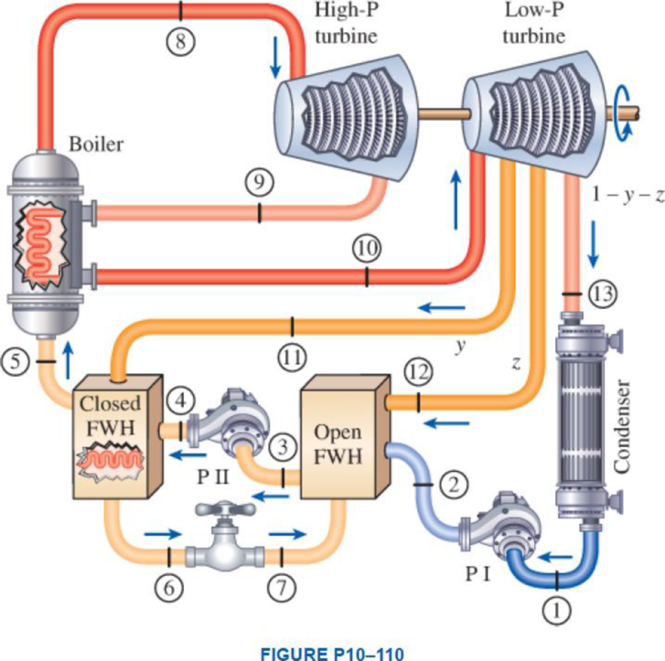
A steam power plant operates on an ideal reheat–regenerative Rankine cycle with one reheater and two feedwater heaters, one open and one closed. Steam enters the high-pressure turbine at 15 MPa and 600°C and the low-pressure turbine at 1 MPa and 500°C. The condenser pressure is 5 kPa. Steam is extracted from the turbine at 0.6 MPa for the closed feedwater heater and at 0.2 MPa for the open feedwater heater. In the closed feedwater heater, the feedwater is heated to the condensation temperature of the extracted steam. The extracted steam leaves the closed feedwater heater as a saturated liquid, which is subsequently throttled to the open feedwater heater. Show the cycle on a T-s diagram with respect to saturation lines. Determine (a) the fraction of steam extracted from the turbine for the open feedwater heater, (b) the thermal efficiency of the cycle, and (c) the net power output for a mass flow rate of 42 kg/s through the boiler.
(a)
The fraction of steam extracted from the turbine for the open feed water heater.
Answer to Problem 107RP
The fraction of steam extracted from the turbine for the open feed water heater is
Explanation of Solution
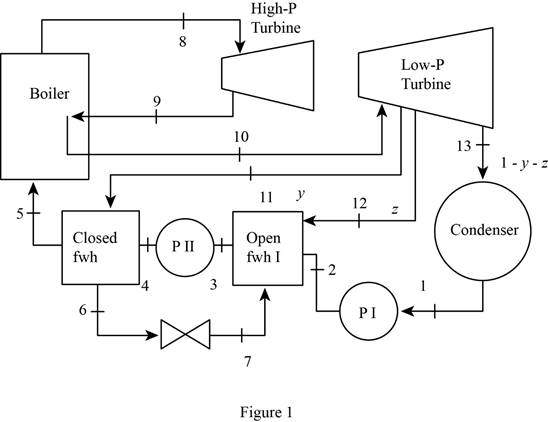
Draw the schematic layout of the given power plant that operates on an ideal reheat-regenerative Rankine cycle as shown in Figure 1.
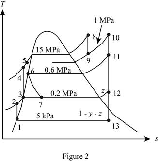
Draw the
Figure 2.
Here, water (steam) is the working fluid of the ideal regenerative Rankine cycle. The cycle involves two pumps.
Write the formula for work done by the pump during process 1-2.
Here, the specific volume is
Write the formula for enthalpy
Write the formula for work done by the pump during process 3-4.
Here, the specific volume is
Write the formula for enthalpy
Write the formula for enthalpy
The quality of water at state 13 is expressed as follows.
The enthalpy at state 13 is expressed as follows.
Here, the enthalpy is
Write the general equation of energy balance equation.
Here, the rate of net energy inlet is
At steady state the rate of change of net energy of the system
Refer Equation (VIII).
Write the energy balance equation for open feed water heater.
Here, the mass fraction steam extracted from the turbine to the inlet mass of the boiler
Rewrite the Equation (IX) in terms of mass fraction
For the open FWH,
Here, the mass fraction steam extracted from the turbine to the inlet mass of the boiler
Solving Equation (XI).
Conclusion:
At state 1:
The water exits the condenser as a saturated liquid at the pressure of
Refer Table A-5, “Saturated water-Pressure table”.
The enthalpy
Substitute
Substitute
From the Table A-5, “Saturated water-temperature Table” obtains the value of the enthalpy
Substitute
Substitute
From the Table A-5, “Saturated water-temperature Table” obtains the value of the enthalpy
Here, the temperature at the state 6
Substitute
From the Table A-6, “Superheated water” obtains the value of the enthalpy
From the Table A-6, “Superheated water” obtains the value of the enthalpy
Here, the entropy at the state 9
From the Table A-6, “Superheated water” obtains the value of the enthalpy
Refer Table A-6, “superheated water”, and write the enthalpy at state 11 at pressure of
Here, enthalpy of saturation liquid at pressure of
Write the formula of interpolation method of two variables.
Here, the variables denote by x and y is specific entropy and specific enthalpy at state 11 respectively.
Show the specific enthalpy at state 11 corresponding to temperature as in Table (1).
|
Specific entropy at state 11 |
Specific enthalpy at state 11 |
| 7.7097 | 3270.8 |
| 7.7642 | |
| 8.0041 | 3483.4 |
Substitute
Substitute
Similarly repeat the Equation (XIV) for specific enthalpy at state 11 corresponding to the pressure of
From the Table A-5, “Saturated water” obtains the value of the specific entropy of saturated liquid
Substitute
Substitute
Substitute
Substitute
Thus, the fraction of steam extracted from the turbine for the open feed water heater is
(b)
The thermal efficiency of the cycle.
Answer to Problem 107RP
The thermal efficiency of the cycle is
Explanation of Solution
Write the formula for heat in
Write the formula for net power output of the cycle per unit mass.
Write the formula for thermal efficiency of the cycle
Conclusion:
Substitute
Substitute 0.06215 for
Substitute
Substitute
Thus, the thermal efficiency of the cycle is
(c)
The net power output for mass flow rate of
Answer to Problem 107RP
The net power output for mass flow rate of
Explanation of Solution
Write the expression for net power output for mass flow rate of
Here, the mass flow rate through the boiler is
Conclusion:
Substitute
Thus, the net power output for mass flow rate of
Want to see more full solutions like this?
Chapter 10 Solutions
Thermodynamics: An Engineering Approach
Additional Engineering Textbook Solutions
Modern Database Management
Starting Out with Programming Logic and Design (5th Edition) (What's New in Computer Science)
Elementary Surveying: An Introduction To Geomatics (15th Edition)
Mechanics of Materials (10th Edition)
Java: An Introduction to Problem Solving and Programming (8th Edition)
Fluid Mechanics: Fundamentals and Applications


- Calculate the mean piston speed (in mph) for a Formula 1 engine running at 14,750 rpm with a bore of 80mm and a stroke of 53mm. Estimate the average acceleration imparted on the piston as it moves from TDC to 90 degrees ATDCarrow_forwardCalculate the compression ratio of an engine with a stroke of 4.2inches a bore of 4.5 inches and a clearance volume of 6.15 cubic inches. Discuss whether or not this is a realistic compression ratio for a street engine and what octane rating of fuel it would need to run correctlyarrow_forwardDraw the free-body diagram for the pinned assembly shown. Find the magnitude of the forces acting on each member of the assembly. 1500 N 1500 N C 45° 45° 45° 45° 1000 mmarrow_forward
- An elastic bar of length L spins with angular velocity ω about an axis, as shown in the figure below. The radial acceleration at a generic point x along the bar is a(x) = ω 2 x. Due to this radial acceleration, the bar stretches along x with displacement function u(x). The displacement u(x) is governed by the following equations: ( d dx (σ(x)) + ρa(x) = 0 PDE σ(x) = E du dx Hooke’s law (1) where σ(x) is the axial stress in the rod, ρ is the mass density, and E is the (constant) Young’s modulus. The bar is pinned on the rotation axis at x = 0, and it is free at x = L. Determine:1. Appropriate BCs for this physical problem.2. The displacement function u(x).3. The stress function σ(x).arrow_forwardWith reference to the given figure: a) Draw a free-body diagram of the structure supporting the pulley. b) Draw shear and bending moment diagrams for both the vertical and horizontal portions of the structure. 48 in. 100 lb 12 in. Cable 27 in. 12-in. pulley radius 100 lb Cablearrow_forwardConsider a standard piston engine . Draw a free body diagram of the piston. Then:a) For an A SI engine with a 100 mm bore at an instantaneous cylinder pressure of 42 bar i. Calculate the level of the combustion gas loading force on the wrist pin in kN. b) Repeat this calculationfor a forced-induction Diesel engine with a 145 mm boreat a cylinder pressure of 115 bararrow_forward
- A punch press with flywheel adequate to minimize speed fluctuation produces 120 punching strokes per minute, each providing an average force of 2000 N over a stroke of 50 mm. The press is driven through a gear reducer by a shaft rotating 200 rpm. Overall efficiency is 80%. a) What power (W) is transmitted through the shaft? b) What average torque is applied to the shaft?arrow_forward1.58 The crankshaft of a single-cylinder air compressor rotates 1800 rpm. The piston area is 2000 mm2 and the piston stroke is 50 mm. Assume a simple “idealized” case where the average gas pressure acting on the piston during the compression stroke is 1 MPa, and pressure during the intake stroke is negligible. The compressor is 80% efficient. A flywheel provides adequate control of the speed fluctuation. a) What motor power (kW) is required to drive the crankshaft? b) What torque is transmitted through the crankshaft?arrow_forward28. The shaft shown in Figure P5-28 is supported by bear- ings at each end, which have bores of 20.0 mm. Design the shaft to carry the given load if it is steady and the shaft is stationary. Make the dimension a as large as pos- sible while keeping the stress safe. Determine the required d 20 mm 5.4 kN d D = ? Length not to scale -α = = -125 mm 20 mm a = -250 mm- FIGURE P5-28 (Problems 28, 29, and 30)arrow_forward
- The motor shown operates at constant speed and develops a torque of 100 lb-in during normal operation. Attached to the motor shaft is a gear reducer of ratio 5:1, that is, the reducer output shaft rotates in the same direction as the motor but at one-fifth motor speed. Rotation of the reducer housing is prevented by the "torque arm" pin-connected at each end as shown. The reducer output shaft drives the load through a flexible coupling. Neglecting gravity and friction, what loads are applied to (a) the torque arm, (b) the motor output shaft, and (c) the reducer output shaft? Motor Gear reducer Flexible coupling (To load) Torque arm- Torque arm Reducer output shaft Motor Reducer Shaft rotationarrow_forwardPlease can you help with ten attatched question?arrow_forwardAn AISI 1018 steel ball with 1.100-in diameter is used as a roller between a flat plate made from 2024 T3 aluminum and a flat table surface made from ASTM No. 30 gray cast iron. Determine the maximum amount of weight that can be stacked on the aluminum plate without exceeding a maximum shear stress of 19.00 kpsi in any of the three pieces. Assume the figure given below, which is based on a typical Poisson's ratio of 0.3, is applicable to estimate the depth at which the maximum shear stress occurs for these materials. 1.0 0.8 Ratio of stress to Pmax 0.4 90 0.6 στ Tmax 0.2 0.5a a 1.5a 2a 2.5a За Distance from contact surface The maximum amount of weight that can be stacked on the aluminum plate is lbf.arrow_forward
 Elements Of ElectromagneticsMechanical EngineeringISBN:9780190698614Author:Sadiku, Matthew N. O.Publisher:Oxford University Press
 Mechanics of Materials (10th Edition)Mechanical EngineeringISBN:9780134319650Author:Russell C. HibbelerPublisher:PEARSON
 Thermodynamics: An Engineering ApproachMechanical EngineeringISBN:9781259822674Author:Yunus A. Cengel Dr., Michael A. BolesPublisher:McGraw-Hill Education
 Control Systems EngineeringMechanical EngineeringISBN:9781118170519Author:Norman S. NisePublisher:WILEY
 Mechanics of Materials (MindTap Course List)Mechanical EngineeringISBN:9781337093347Author:Barry J. Goodno, James M. GerePublisher:Cengage Learning
 Engineering Mechanics: StaticsMechanical EngineeringISBN:9781118807330Author:James L. Meriam, L. G. Kraige, J. N. BoltonPublisher:WILEY