
Videos
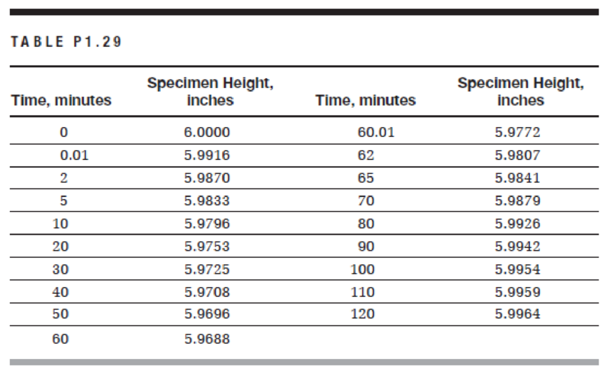
An asphalt concrete cylindrical specimen with a 4-in. diameter and a 6-in. height is subjected to an axial compressive static load of 150 lb for 1 hour, after which the load is removed. The test was performed at a temperature of 100°F. The height of the specimen was measured at different time intervals during loading and unloading for a total of 2 hours and produced the results shown in Table P1.29.
a. Using a spreadsheet program, plot the stress versus time and the strain versus time on two separate graphs.
b. How much is the elastic strain?
c. What is the permanent strain at the end of the experiment?
d. What is the phenomenon of the change of specimen height during static loading called? What is the phenomenon of the change of specimen height during unloading called?

Trending nowThis is a popular solution!

Chapter 1 Solutions
Materials for Civil and Construction Engineers (4th Edition)
Additional Engineering Textbook Solutions
Computer Science: An Overview (13th Edition) (What's New in Computer Science)
Degarmo's Materials And Processes In Manufacturing
Starting Out With Visual Basic (8th Edition)
Concepts Of Programming Languages
Java: An Introduction to Problem Solving and Programming (8th Edition)
Web Development and Design Foundations with HTML5 (8th Edition)


- The influence line for moment at B for the beam shown is A -6 m- B a. O at A, 6 at B, and 15 at C b. 1 at A, 1 at B, and 1 at C c. O at A, 0 at B, and -9 at C d. O at A, 1 at B, and 1 and C -9 m-arrow_forwardConsider the following figure: H/3 Pa Given: H = 7 m, y = 13 kN/m³, ø′ = 25°, c′ = 12 kN/m², and a = 10°. For given values, K₁ = 0.296. Calculate the Rankine active force per unit length of the wall after the occurrence of the tensile crack. (Enter your answer to three significant figures.) Pa = kN/marrow_forwardWall movement to left 45+ '/2 45 + 6'/2 Rotation of wall about this point A vertical retaining wall shown in the figure above is 7 m high with a horizontal backfill. For the backfill, assume that y = 14.5 kN/m³, ' = 26°, and c′ = 18 kN/m². Determine the Rankine active force per unit length of the wall after the occurrence of the tensile crack. (Enter your answer to three significant figures.) Pa = kN/marrow_forward
- Consider the following figure: 0.6 "d 0.5 k₁ = 0 0.4 03 =0 kh = 0.2 0.3 0.025 0.2 0.05 0.1 0.1 0.2 0 -0.1 ↓ 0 5 10 15 20 25 30 35 40 45 ' (deg) For a retaining wall with a vertical back and horizontal backfill with a c'-' soil, the following are given: H = 10 ft Y = 111 lb/ft³ ' = 25° kh = 0.2 k₁ = 0 c = 113 lb/ft² Determine the magnitude of active force Pae on the wall. (Enter your answer to two significant figures.) Pae = lb/ftarrow_forwardA 13.0 ft high vertical wall retains an overconsolidated soil where OCR = 1.5, c' = 0, and ' magnitude and the location of the horizontal load on the wall, assuming the at-rest condition. Use Ysat (Enter your answers to three significant figures.) 33°. If the entire soil behind the wall is submerged with the water level at the ground surface, determine the 127 lb/ft³. Activity Frame P₁ = lb/ft Height above the bottom of the wall = O Icon Kov ftarrow_forward= A 5 m high smooth vertical wall retains a clay backfill with c = 13 kN/m², ' -25°, and y = 17.0 kN/m³. The clay is in active state. a. Determine the maximum tensile stress within the clay. (Enter your answer to three significant figures.) σα = kN/m² b. Determine the depth of the tensile cracks. (Enter your answer to three significant figures.) Zo = m c. Determine the magnitude and location of the active thrust, neglecting the tensile zone. (Enter your answers to three significant figures.) Pa x = = kN/m² marrow_forward
- A composite beam is fabricated by bolting two 3.1-in.-wide by 14-in.-deep timber planks to the sides of a 0.4-in. by 14-in. steel plate. The moduli of elasticity of the timber and the steel are 1940 ksi and 30300 ksi, respectively. The simply supported beam spans a distance of 21 ft and carries two concentrated loads P, which are applied as shown. Assume LAB = LCD = 5 ft, Lgc = 11 ft, b = 3.1 in., d = 14 in. and t = 0.4 in. (a) Determine the maximum bending stresses σ,, σ, produced in the timber planks and the steel plate if P = 2.1 kips. (b) Assume that the allowable bending stresses of the timber and the steel are 830 psi and 24900 psi, respectively. Determine the largest acceptable magnitude for concentrated loads P. (You may neglect the weight of the beam in your calculations.) LAB B Answers: LCD LBC b Cross section D ksi, σ, = i ksi. (a) σ, = (b) P= i i kips.arrow_forwardThe internal shear force at a certain section of a steel beam is V = 107 kips. If the beam has the cross section shown, determine the shear stress at point H, which is located 2 in. below the top surface of the flanged shape. The centroid is 5.283 in. above the bottom surface of the beam, and the moment of inertia about the z axis is 465.8 in.4. 5 in. 2 in. H 业 1 in. 1 in. 12 in. 8 in. 1 in. 11.51 ksi O 9.72 ksi 8.34 ksi 6.03 ksi ○ 7.73 ksiarrow_forwardThe beam shown will be constructed from a standard steel W-shape using an allowable bending stress of 33.6 ksi. Assume P = 70 kips. L₁ = 2.2 ft, and L2 = 6.6 ft. (a) Determine the minimum section modulus required for this beam. (b) From the table below, select the lightest W shape that can be used for this beam. (c) What is the total weight of the steel beam itself (ie, not including the loads that are carried by the beam)? Lu B D L2 L₁ Wide-Flange Sections or W Shapes-U.S. Customary Units x x be Web Area Depth thickness Flange width Flange thickness Designation A d Tw by 4 S₁ و" in.² in. in. in. in. in,4 in.³ in. in.4 in,³ in. W24 x 94 27.7 24.3 0.515 9.07 0.875 2700 222 9.87 109 24.0 1.98 24 x 76 22.4 23.9 0.440 8.99 0.680 2100 176 9.69 82.5 18.4 1.92 24 x 68 20.1 23.7 0.415 8.97 0.585 1830 154 9.55 70.4 15.7 1.87 24 x 55 16.2 23.6 0.395 7.01 0.505 1350 114 9.11 29.1 8.30 1.34 W21 x 68 20.0 21.1 0.430 8.27 0.685 1480 140 8.60 64.7 15.7 1.80 21 x 62 18.3 21.0 0.400 8.24 0.615 1330 127…arrow_forward
- A composite beam is made of two brass [E=114 GPa] bars bonded to two aluminum [E = 74 GPa] bars, as shown. The beam is subjected to a bending moment of 335 N-m acting about the z axis. Using a = 5 mm, b = 30 mm, c = 10 mm, and d = 20 mm, calculate (a) the maximum bending stress in the aluminum bars. (b) the maximum bending stress in the brass bars. N Aluminum C Brass Brass Aluminum b Answers: (a) σal= (b) Obr= a a MPa MPaarrow_forwardA standard steel pipe (D = 3.500 in.; d = 3.068 in.) supports a concentrated load of P = 630 lb as shown. The span length of the cantilever beam is L = 4 ft. Determine the magnitude of the maximum horizontal shear stress in the pipe. 720 psi 761 psi 508 psi 564 psi 667 psi L Pipe cross section.arrow_forwardA beam is subjected to equal bending moments of M₂ = 59 kip-ft. The cross-sectional dimensions are b₁ = 7.5 in., d₁ = 1.4 in., b₂ = 0.55 in., d₂ = 5.0 in., b3 = 3.2 in., and d3 = 1.5 in. Determine: (a) the centroid location (measured with respect to the bottom of the cross-section), the moment of inertia about the z axis, and the controlling section modulus about the z axis. (b) the bending stress at point H. Tensile stress is positive, while compressive stress is negative. (c) the bending stress at point K. Tensile stress is positive, while compressive stress is negative. (d) the maximum bending stress produced in the cross section. Tensile stress is positive, while compressive stress is negative. M₂ Z M₂ Answer: (a) y= i Iz= in. in.4 S= i on,3 (b) σH= i ksi (c) OK = i ksi (d) σmax= ksi K b₁ d₁ H b₂ b3 d₂ d3arrow_forward
 Fundamentals of Geotechnical Engineering (MindTap...Civil EngineeringISBN:9781305635180Author:Braja M. Das, Nagaratnam SivakuganPublisher:Cengage Learning
 Steel Design (Activate Learning with these NEW ti...Civil EngineeringISBN:9781337094740Author:Segui, William T.Publisher:Cengage Learning
 Traffic and Highway EngineeringCivil EngineeringISBN:9781305156241Author:Garber, Nicholas J.Publisher:Cengage Learning
 Materials Science And Engineering PropertiesCivil EngineeringISBN:9781111988609Author:Charles GilmorePublisher:Cengage Learning
 Solid Waste EngineeringCivil EngineeringISBN:9781305635203Author:Worrell, William A.Publisher:Cengage Learning,
 Construction Materials, Methods and Techniques (M...Civil EngineeringISBN:9781305086272Author:William P. Spence, Eva KultermannPublisher:Cengage Learning