
Materials for Civil and Construction Engineers (4th Edition)
4th Edition
ISBN: 9780134320533
Author: Michael S. Mamlouk, John P. Zaniewski
Publisher: PEARSON
expand_more
expand_more
format_list_bulleted
Concept explainers
Videos
Textbook Question
Chapter 1, Problem 1.11QP
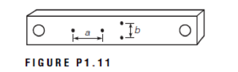
The rectangular block shown in Figure P1.11 is subjected to tension within the elastic range. The increase in the length of a is 2 × 10⁻³ in. and the contraction of b is 3.25 × 10⁻⁴ in. If the original lengths of a and b were 2 in. and 1 in., respectively, what is Poisson’s ratio for the material of the specimen?
Expert Solution & Answer
Want to see the full answer?
Check out a sample textbook solution
Students have asked these similar questions
Draw the shear and moment diagrams of the beam CDE showing all calculations. Assume the support at A is a roller and B is a pin. There are fixed connected joints at D and E. Assume P equals 9.6 and w equals 0.36
Find the length of the diagonal on
the x-z plane (square root of
square of sides).
Find angle between the vector F
and its projection on x-z (the
diagonal defined above).
Find Horizontal Projection of F on
x-z plane, Fh, and vertical
component, FY.
Find projections of Fh, to define
in-plane components Fx and Fz.
Show that results match those of
Problem 2(a) above.
(2,0,4)
F₂
100 N
(5, 1, 1)
For the control system Draw Nyquist Plot with
Solution
G(S)= 63.625 (S+1)(S+3)
S(S+2)(5+65+18) (5+5)
Chapter 1 Solutions
Materials for Civil and Construction Engineers (4th Edition)
Ch. 1 - State three examples of a static load application...Ch. 1 - A material has the stressstrain behavior shown in...Ch. 1 - A tensile load of 50.000 lb is applied to a metal...Ch. 1 - A tensile load of 190 kN is applied to a round...Ch. 1 - A cylinder with a 6.0 in. diameter and 12.0 in....Ch. 1 - A metal rod with 0.5 inch diameter is subjected to...Ch. 1 - A rectangular block of aluminum 30 mm 60 mm 90...Ch. 1 - A plastic cube with a 4 in. 4 in. 4 in. is...Ch. 1 - A material has a stressstrain relationship that...Ch. 1 - On a graph, show the stressstrain relationship...
Ch. 1 - The rectangular block shown in Figure P1.11 is...Ch. 1 - The rectangular metal block shown in Figure P1.11...Ch. 1 - A cylindrical rod with a length of 380 mm and a...Ch. 1 - A cylindrical rod with a radius of 0.3 in. and a...Ch. 1 - A cylindrical rod with a diameter of 15.24 mm and...Ch. 1 - The stressstrain relationship shown in Figure...Ch. 1 - A tension test performed on a metal specimen to...Ch. 1 - An alloy has a yield strength of 41 ksi, a tensile...Ch. 1 - Prob. 1.21QPCh. 1 - Figure P1.22 shows (i) elasticperfectly plastic...Ch. 1 - An elastoplastic material with strain hardening...Ch. 1 - A brace alloy rod having a cross sectional area of...Ch. 1 - A brass alloy rod having a cross sectional area of...Ch. 1 - A copper rod with a diameter of 19 mm, modulus of...Ch. 1 - A copper rod with a diameter of 0.5 in., modulus...Ch. 1 - Define the following material behavior and provide...Ch. 1 - An asphalt concrete cylindrical specimen with a...Ch. 1 - What are the differences between modulus of...Ch. 1 - Prob. 1.33QPCh. 1 - A metal rod having a diameter of 10 mm is...Ch. 1 - What is the factor of safety? On what basis is its...Ch. 1 - Prob. 1.36QPCh. 1 - Prob. 1.37QPCh. 1 - A steel rod, which is free to move, has a length...Ch. 1 - In Problem 1.38, if the rod is snugly fitted...Ch. 1 - A 4-m-long steel plate with a rectangular cross...Ch. 1 - Estimate the tensile strength required to prevent...Ch. 1 - Prob. 1.42QPCh. 1 - Briefly discuss the variability of construction...Ch. 1 - In order to evaluate the properties of a material,...Ch. 1 - A contractor claims that the mean compressive...Ch. 1 - A contractor claims that the mean compressive...Ch. 1 - Prob. 1.47QPCh. 1 - Prob. 1.48QPCh. 1 - Prob. 1.49QPCh. 1 - Briefly discuss the concept behind each of the...Ch. 1 - Referring to the dial gauge shown in Figure P1.51,...Ch. 1 - Repeat Problem 1.51 using the dial gauge shown in...Ch. 1 - Measurements should be reported to the nearest...Ch. 1 - During calibration of an LVDT, the data shown in...Ch. 1 - During calibration of an LVDT, the data shown in...
Additional Engineering Textbook Solutions
Find more solutions based on key concepts
1.2 Explain the difference between geodetic and plane
surveys,
Elementary Surveying: An Introduction To Geomatics (15th Edition)
How are relationships between tables expressed in a relational database?
Modern Database Management
17–1C A high-speed aircraft is cruising in still air. How does the temperature of air at the nose of the aircra...
Thermodynamics: An Engineering Approach
Assume a telephone signal travels through a cable at two-thirds the speed of light. How long does it take the s...
Electric Circuits. (11th Edition)
The following C++ program will not compile because the lines have been mixed up. cout Success\n; cout Success...
Starting Out with C++ from Control Structures to Objects (9th Edition)
What is the importance of modeling in engineering? How are the mathematical models for engineering processes pr...
HEAT+MASS TRANSFER:FUND.+APPL.
Knowledge Booster


Learn more about
Need a deep-dive on the concept behind this application? Look no further. Learn more about this topic, civil-engineering and related others by exploring similar questions and additional content below.Similar questions
- Q3: Find the support reactions at A: y mm A P=last 2 student's ID#+100 (N) 124N last 3 student's ID# (mm) 724mm 20 mm D B C X last 3 student's ID#+20 mm 744mm 40 mm 60 mmarrow_forwardA hoist trolley is subjected to the three forces shown. Knowing that α = 40°, determine (a) the required magnitude of the force P if the resultant of the three forces is to be vertical, (b) the corresponding magnißide of the resultant. α 724lb last 3 student's ID# lb α last 2 student's ID#+100 lb 124lb Parrow_forwardFive wood boards are bolted together to form the built-up beam shown in the figure. The beam is subjected to a shear force of V = 13 kips. Each bolt has a shear strength of Vbolt = 6 kips. [h₁ =4.25 in., t₁ = 0.5 in., h₂ = 6 in., t₂ = 1 in.] hi + hi/2 h:/2 h: 2 h + h/2 Determine the moment of inertia of the section. Determine the maximum allowable spacing of the bolts. Determine the shear flow in the section connected by fasteners.arrow_forward
- A vessel has a diameter of 1m and 2m high is moving downward with a positive acceleration of 3m/s2. The pressure at the bottom of the liquid is 9.534kPa, determine the mass of the liquid.arrow_forwardYou are the engineer asked to design a rapid sand filtration system for a small water treatment plant. It has the following characteristics: Hydraulic loading rate = 6 m/h Total volumetric flow rate of the plant = 3 MGD Effective filtration rate = 5.8 m/h Production efficiency = 97% Complete (filtration, rinsing, and backwashing) filter cycle duration = 48 h What is the area of your square filtration system? What are the surface dimensions of the filter? What volume of water is needed for backwashing plus rinsing the filter in each rinsing cycle?arrow_forwardFive wood boards are bolted together to form the built-up beam shown in the figure. The beam is subjected to a shear force of V = 14 kips. Each bolt has a shear strength of V bolt = 6 kips. [h₁ = 4 in., t₁ = 0.75 in., h₂ = 6.5 in., t₂ = 1.25 in.] h/2 + hi/2 h:/2 h: 2 hi + hiz Determine the moment of inertia of the section. Calculate the shear force in each bolt. Calculate the shear stress in the bolts.arrow_forward
- A box beam is fabricated from two plywood webs that are secured to lumber boards at its top and bottom flanges. The beam supports a concentrated load of P = 4100 lb at the center of a 13-ft span. Bolts (3/8-in. diameter) connect the plywood webs and the lumber flanges at a spacing of s = 9 in. along the span. Supports A and C can be idealized as a pin and a roller, respectively. [w = 4.5 in., b = 0.25 in., t = 5 in., h = 17 in.] B Determine the maximum horizontal shear stress in the plywood webs. Determine the average shear stress in the bolts. Determine the maximum bending stress in the lumber flanges.arrow_forwardA cantilever flexural member is fabricated by bolting two identical C- section steel shapes back to back as shown in the figure. The beam has a span of L = 1300 mm and supports a concentrated load of P = 800 N. The cross-sectional dimensions of the built- up shape are shown in the figure. Assume the section has a constant thickness of t = 2.5 mm. Bolts of 3.5 mm diameter are installed at intervals of s = 65 mm.[b = 100 mm, a = 25 mm] b T Determine the shear flow in the sections connected by the fasteners. Calculate the shear force in each bolt. Calculate the shear stress in the bolts.arrow_forwardFive wood boards are bolted together to form the built-up beam shown in the figure. The beam is subjected to a shear force of V = 14 kips. Each bolt has a shear strength of V bolt = 6 kips. [h₁4 in., t₁ = 0.75 in., h₂ = 6.5 in., t₂ = 1.25 in.] hi/2 h/2 h2 h:/2 hi/2 + h2 Determine the moment of inertia of the section. Determine the shear flow in the section connected by fasteners. Determine the maximum allowable spacing of the bolts.arrow_forward
- Two built-up beams shown in the figure below have the same dimensions and are connected by the same types of nails with the same spacing. Which beam could carry more shear force if the controlling factor is the shear flow in the fasteners? Nails Beam (1) Z Beam (2) Beam (2) Beam (1) Both are the same Cannot answer without knowing the shear diagram Cannot answer without knowing the modulus of rigidity Nailsarrow_forwardTwo built-up beams shown in the figure below have the same dimensions and are connected by the same types of nails with the same spacing. Which beam could carry more shear force if the controlling factor is the shear flow in the fasteners? Nails Beam (1) Beam (2) Cannot answer without knowing the shear diagram Beam (1) Cannot answer without knowing the modulus of Nailsarrow_forward8-51. Determine the horizontal displacement at C. Take E = 29(10³) ksi, I = 150 in for each member. Use the method of virtual work. 8ft 10 ft Barrow_forward
arrow_back_ios
SEE MORE QUESTIONS
arrow_forward_ios
Recommended textbooks for you
 Materials Science And Engineering PropertiesCivil EngineeringISBN:9781111988609Author:Charles GilmorePublisher:Cengage Learning
 Steel Design (Activate Learning with these NEW ti...Civil EngineeringISBN:9781337094740Author:Segui, William T.Publisher:Cengage Learning
 Principles of Foundation Engineering (MindTap Cou...Civil EngineeringISBN:9781337705028Author:Braja M. Das, Nagaratnam SivakuganPublisher:Cengage Learning
 Engineering Fundamentals: An Introduction to Engi...Civil EngineeringISBN:9781305084766Author:Saeed MoaveniPublisher:Cengage Learning
Materials Science And Engineering Properties
Civil Engineering
ISBN:9781111988609
Author:Charles Gilmore
Publisher:Cengage Learning
Steel Design (Activate Learning with these NEW ti...
Civil Engineering
ISBN:9781337094740
Author:Segui, William T.
Publisher:Cengage Learning
Principles of Foundation Engineering (MindTap Cou...
Civil Engineering
ISBN:9781337705028
Author:Braja M. Das, Nagaratnam Sivakugan
Publisher:Cengage Learning
Engineering Fundamentals: An Introduction to Engi...
Civil Engineering
ISBN:9781305084766
Author:Saeed Moaveni
Publisher:Cengage Learning
Material Properties 101; Author: Real Engineering;https://www.youtube.com/watch?v=BHZALtqAjeM;License: Standard YouTube License, CC-BY