
(a)
The design of a three-plate moment connection of a
Answer to Problem 8.6.4P
Use a
1/8-in. fillet weld on both sides of the plate.
Use a
Explanation of Solution
Given:
Service dead-load moment = 42 ft-kips
Service live-load moment = 104 ft-kips
Service dead-load beam reaction = 8 kips
Service live-load beam reaction = 21 kips
Group A bearing type bolts
E70 electrodes
A992 steel- Beam and column
A36 steel- Plate material
Calculation:
Reaction:
Moment:
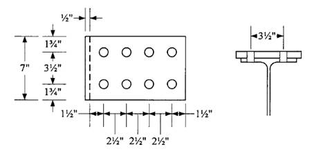
Web plate:
Neglect eccentricity.
Try 5/8-in. diameter bolts.
Assume that threads are in the plane of shear.
Shear capacity of one bolt is
Number of bolts required is
Try 4 bolts.
Determine plate thickness required for bearing. Assume that
Load resisted by each bolt =
Let
Try
Determine whether plate or beam web controls bearing. For the plate,
For the beam web,
Therefore, plate controls.
Check bearing strength assumption:
For the hole nearest the edge, minimum
Try
Therefore, use
For other bolts, minimum
Use
Therefore, use
Bearing controls over shear at each bolt location. Total strength is
Use four 5/8-in. diameter Group A bolts.

Determine plate thickness required for shear:
Shear yielding strength is
Let
Try
Check shear rupture strength:
Use hole diameter =
Check block shear:
Shear areas:
Tension area:
with an upper limit of
The nominal block shear strength is therefore 64.92 kips. The design block shear strength is
Use a
Connection of shear plate to column flange:
Use E70 electrodes
Minimum weld size, based on the plate thickness, is 1/8-in. try
Weld strength =
Base metal (plate) shear strength:
Yielding:
Rupture:
Total length required =
Use a continuous 1/8-in. fillet weld, both sides of plate.
Flange plate:
From
Try 7/8-in. diameter bolts.
Assume that threads are in the plane of shear.
Number of bolts required for shear is
Try 8 bolts (4 pair)
Determine plate thickness required for bearing:
Minimum
Use
Minimum
Use
For the hole nearest the edge,
Therefore, use
For other bolts,
Therefore, use
Total connection strength =
Let
Design top flange plate as a tension connection element
Tension on gross area:
Required
Tension on net area:
Required
Try a plate width of
For gross area requirement,
For net area requirement,
Hole diameter =
Try a plate
Check compression in the bottom plate:
Assume that the plate acts as a fixed-end compression member between the end fastener and the weld. Use
For compression elements with
Therefore,
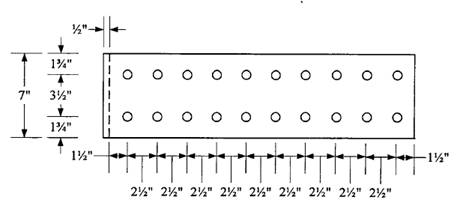
Check block shear on the plate using the dimensions and bolt layout shown.

Shear areas:
Tension area:
with an upper limit of
The nominal block shear strength is therefore 395.9 kips. The design block shear strength is
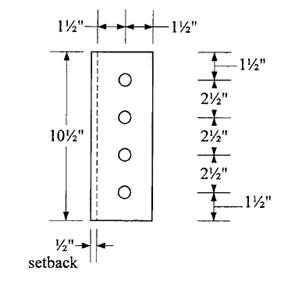
Check block shear strength of beam flange:
Transverse spacing = gauge distance = 3.5 in.
Transverse edge distance =
Longitudinal spacing and edge distance same as for plate.
Shear areas:
Tension area:
with an upper limit of
The nominal block shear strength is therefore 199.7 kips.
The design block shear strength is
Check beam for the effect of bolt holes in the tension flange:
The gross area of one flange is
The effective hole diameter is
Since
Try a smaller diameter bolt. Try ½-in. diameter bolts.
Normal shearing strength =
Number of bolts required for shear is
Try 20 bolts (10 pair)
Bearing and block shear will be satisfactory.
Check reduction in beam flange area:
Use a hole diameter =
Since
Plate length =
Conclusion:
Use a
(b)
The design of a three-plate moment connection of a
Answer to Problem 8.6.4P
Use a
1/8-in. fillet weld on both sides of the plate.
Use a
Explanation of Solution
Given:
Service dead-load moment = 42 ft-kips
Service live-load moment = 104 ft-kips
Service dead-load beam reaction = 8 kips
Service live-load beam reaction = 21 kips
Group A bearing type bolts
E70 electrodes
A992 steel- Beam and column
A36 steel- Plate material
Calculation:
Reaction:
Moment:
Web plate:
Neglect eccentricity.
Try 5/8-in. diameter bolts.
Assume that threads are in the plane of shear.
Shear capacity of one bolt is
Number of bolts required is
Try 4 bolts.
Determine plate thickness required for bearing. Assume that
Load resisted by each bolt =
Let
Try
Determine whether plate or beam web controls bearing. For the plate,
For the beam web,
Therefore, plate controls.
Check bearing strength assumption:
For the hole nearest the edge, minimum
Try
Therefore, use
For other bolts, minimum
Use
Therefore, use
Bearing controls over shear at each bolt location.
Total strength is
Use four 5/8-in. diameter Group A bolts.
Determine plate thickness required for shear:
Shear yielding strength is
Let
Try
Check shear rupture strength:
Use hole diameter =
Check block shear:
Shear areas:
Tension area:
with an upper limit of
The nominal block shear strength is therefore 64.92 kips. The design block shear strength is
Use a
Connection of shear plate to column flange:
Use E70 electrodes.
Minimum weld size, based on the plate thickness, is 1/8-in. try
Weld strength =
Base metal (plate) shear strength:
The allowable shear yield strength per unit length is
The base metal allowable shear rupture strength per unit length is
Total length required =
Use a continuous 1/8-in. fillet weld, both sides of plate.
Flange plate:
From
Try 7/8-in. diameter bolts.
Assume that threads are in the plane of shear.
Number of bolts required for shear is
Try 8 bolts (4 pair)
Determine plate thickness required for bearing:
Minimum
Use
Minimum
Use
For the hole nearest the edge,
Therefore, use
For other bolts,
Therefore, use
Total connection strength =
Let
Design top flange plate as a tension connection element
Tension on gross area:
Required
Tension on net area:
Required
Try a plate width of
For gross area requirement,
For net area requirement,
Hole diameter =
Try a plate
Check compression in the bottom plate:
Assume that the plate acts as a fixed-end compression member between the end fastener and the weld. Use
For compression elements with
Therefore,
Check block shear on the plate using the dimensions and bolt layout shown.
Shear areas:
Tension area:
with an upper limit of
The nominal block shear strength is therefore 395.9 kips. The design block shear strength is
Check block shear strength of beam flange:
Transverse spacing = gauge distance = 3.5 in.
Transverse edge distance =
Longitudinal spacing and edge distance same as for plate.
Shear areas:
Tension area:
with an upper limit of
The nominal block shear strength is therefore 199.7 kips.
The design block shear strength is
Check beam for the effect of bolt holes in the tension flange:
The gross area of one flange is
The effective hole diameter is
Since
Try a smaller diameter bolt. Try ½-in. diameter bolts.
Normal shearing strength =
Number of bolts required for shear is
Try 20 bolts (10 pair)
Bearing and block shear will be satisfactory.
Check reduction in beam flange area:
Use a hole diameter =
Since
Plate length =
Conclusion:
Use a

Want to see more full solutions like this?
Chapter 8 Solutions
Steel Design (Activate Learning with these NEW titles from Engineering!)

- Determine forces in members BC, GF and CG and nature of forces 9 m D 4 m C 4m 500 F 4 kN 6 kN 4 m 3 m B3 G E Assignment-2 Aarrow_forwardFind forces in all members of the truss shown in Fig. Also find reactions at supports. 12 kN 20 kN ΙΟΧΟΙΟΙ 2 m 2 m 2 m 3 m C G E 4 m B Determine forces in members BC, GF and CG and nature of forces 9 m D 4 m C 4 m F 4 kN 6 kN 4 m 3 m B3 C E Assignment-2arrow_forwardPart 3: Problem-Solving. Solve the following problems. Show all calculations. 1. A retaining wall 5.80m high supports soil that has the following properties: Unit weight = 17.3 kN/m³ Angle of internal friction = 26 deg. Cohesion = 14.5 kPa a) Calculate the normal pressure acting at the back of the wall assuming no tensile crack occurs in the soil. b) Find the location of the tensile crack measured from the surface of horizontal backfill. c) Determine the active pressure acting on the wall in tensile crack occurs in the soil. 2. The soil material is supported by a retaining wall to a height of 6m. The unit weight of the soil is 16 kN/m³ and the angle of internal friction is 29 deg. Assume the soil is cohesionless. a) Determine the earth pressure on the wall. b) Find the total active pressure if surcharge of 14 kPa is applied on the surface of horizontal backfill. c) Locate the position of the total pressure from the bottom.arrow_forward
- Question 3 (20 points): The traffic volume on a 2-lane highway is 1600 veh/hr in each direction Page 3 of 6 with a density of 20 veh/mi. A large dump truck enters the traffic stream from an adjacent construction site at 20 mph and carries on this way for 2 miles before turning off to the dump site. Because flow is so high in the opposite direction, no one can pass the truck. As a result, traffic back up behind the truck at four times the density (i.e., 4x20 = 80 veh/mi) at a volume of 1000 veh/hr. How many vehicles get caught in the traffic congestion before the truck exits the highway?arrow_forwardHow can construction project managers find a balance between speeding up schedules and the risks of making more mistakes and needing rework, especially when using methods like fast tracking?arrow_forwardHelp i keep getting the wrong answer. So I must be doing something wrong.arrow_forward
- 6000 units have been installed to date with 9,000 units to install. Labor costs are $23,300.00 to date. What is the unit cost for labor to date?arrow_forwardThe base rate for labor is $15/hr. The labor burden is 35% and 3% for small tools for the labor. There are 1000 units to install. Records indicate that trade workers can install 10 units per hour, per trade worker. The owners need 15% overhead and profit to pay bills, pay interest on loan and provide some profit to the partners. What is the minimum bid assuming no risk avoidance factor?arrow_forwardCan you show me how to obtain these answers thanks, will rate!arrow_forward
 Steel Design (Activate Learning with these NEW ti...Civil EngineeringISBN:9781337094740Author:Segui, William T.Publisher:Cengage Learning