
ENGINEERING CIRCUIT...(LL)>CUSTOM PKG.<
9th Edition
ISBN: 9781260540666
Author: Hayt
Publisher: MCG CUSTOM
expand_more
expand_more
format_list_bulleted
Concept explainers
Videos
Textbook Question
Chapter 8, Problem 57E
For the circuit represented in Fig. 8.82, (a) obtain an expression for v which is valid for all values of t; (b) sketch your result for 0 ≤ t ≤ 3 s.
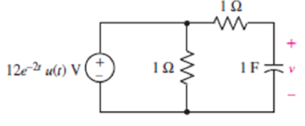
FIGURE 8.82
Expert Solution & Answer
Want to see the full answer?
Check out a sample textbook solution
Students have asked these similar questions
use matlab
I need help with this problem and an explanation of the solution for the image described below. (Introduction to Signals and Systems)
How do we know that D1 is forward bias and D2 is reverse biased?
Chapter 8 Solutions
ENGINEERING CIRCUIT...(LL)>CUSTOM PKG.<
Ch. 8.1 - For the circuit in Fig. 8.2, what value of...Ch. 8.1 - Noting carefully how the circuit changes once the...Ch. 8.2 - In a source-free series RC circuit, find the...Ch. 8.3 - Prob. 4PCh. 8.3 - Prob. 5PCh. 8.4 - Prob. 6PCh. 8.4 - Prob. 7PCh. 8.4 - Prob. 8PCh. 8.5 - Evaluate each of the following at t = 0.8: (a)...Ch. 8.6 - For the circuit of Fig. 8.37, find vc(t) at t...
Ch. 8.7 - Prob. 11PCh. 8.7 - The voltage source 60 40u(t) V is in series with...Ch. 8.7 - Prob. 13PCh. 8.8 - Prob. 14PCh. 8.8 - Prob. 15PCh. 8 - A source-free RC circuit has R = 4 k and C = 22 F,...Ch. 8 - A source-free RC circuit has v(0) = 12 V and R =...Ch. 8 - The resistor in the circuit of Fig. 8.51 has been...Ch. 8 - Prob. 4ECh. 8 - Prob. 5ECh. 8 - Prob. 6ECh. 8 - Prob. 7ECh. 8 - Prob. 8ECh. 8 - Prob. 9ECh. 8 - The switch in Fig. 8.56 has been closed for a long...Ch. 8 - For the circuit in Fig. 8.56, find (a) the total...Ch. 8 - Design a capacitor-based circuit that can achieve...Ch. 8 - (a) Graph the function f (t) = 10e2t over the...Ch. 8 - The current i(t) flowing through a 1 k resistor is...Ch. 8 - Radiocarbon dating has a similar exponential time...Ch. 8 - For the circuit of Fig. 8.4, compute the time...Ch. 8 - Design a circuit which will produce a current of 1...Ch. 8 - Prob. 18ECh. 8 - Prob. 19ECh. 8 - Referring to the circuit shown in Fig. 8.11,...Ch. 8 - Prob. 21ECh. 8 - With the assumption that the switch in the circuit...Ch. 8 - The switch in Fig. 8.57 has been closed since...Ch. 8 - The switch in the circuit of Fig. 8.58 has been...Ch. 8 - Assuming the switch initially has been open for a...Ch. 8 - (a) Obtain an expression for v(t), the voltage...Ch. 8 - For the circuit of Fig. 8.61, determine ix, iL,...Ch. 8 - Prob. 28ECh. 8 - Prob. 29ECh. 8 - Prob. 30ECh. 8 - Prob. 31ECh. 8 - (a) Obtain an expression for vx as labeled in the...Ch. 8 - Prob. 33ECh. 8 - Prob. 34ECh. 8 - Prob. 35ECh. 8 - Prob. 36ECh. 8 - Prob. 37ECh. 8 - The switch in Fig. 8.70 is moved from A to B at t...Ch. 8 - Prob. 39ECh. 8 - Prob. 40ECh. 8 - Evaluate the following functions at t = 1, 0, and...Ch. 8 - Prob. 42ECh. 8 - Prob. 43ECh. 8 - Prob. 44ECh. 8 - You can use MATLAB to represent the unit-step...Ch. 8 - With reference to the circuit depicted in Fig....Ch. 8 - For the circuit given in Fig. 8.75, (a) determine...Ch. 8 - Prob. 48ECh. 8 - Prob. 49ECh. 8 - You build a portable solar charging circuit...Ch. 8 - The switch in the circuit of Fig. 8.78 has been...Ch. 8 - The switch in the circuit of Fig. 8.78 has been...Ch. 8 - Prob. 53ECh. 8 - Prob. 54ECh. 8 - Prob. 55ECh. 8 - For the circuit represented in Fig. 8.82, (a)...Ch. 8 - Prob. 58ECh. 8 - Prob. 59ECh. 8 - For the circuit given in Fig. 8.85, (a) determine...Ch. 8 - The circuit depicted in Fig. 8.86 contains two...Ch. 8 - Prob. 62ECh. 8 - Prob. 63ECh. 8 - A series RL circuit has a voltage that steps from...Ch. 8 - For the two-source circuit of Fig. 8.89, note that...Ch. 8 - (a) Obtain an expression for iL as labeled in Fig....Ch. 8 - Obtain an expression for i(t) as labeled in the...Ch. 8 - Obtain an expression for i1 as indicated in Fig....Ch. 8 - Plot the current i(t) in Fig. 8.93 if (a) R = 10 ;...Ch. 8 - A dc motor can be modeled as a series RL circuit...Ch. 8 - Prob. 71ECh. 8 - Prob. 72ECh. 8 - A series RC sequentially switched circuit has R =...Ch. 8 - Refer to the circuit of Fig. 8.95, which contains...Ch. 8 - In the circuit of Fig. 8.95, a 3 mF capacitor is...Ch. 8 - Prob. 78E
Knowledge Booster


Learn more about
Need a deep-dive on the concept behind this application? Look no further. Learn more about this topic, electrical-engineering and related others by exploring similar questions and additional content below.Similar questions
- Solve it in a different way than the previous solution that I searched forarrow_forwardA lossless uncharged transmission line of length L = 0.45 cm has a characteristic impedance of 60 ohms. It is driven by an ideal voltage generator producing a pulse of amplitude 10V and width 2 nS. If the transmission line is connected to a load of 200 ohms, sketch the voltage at the load as a function of time for the interval 0 < t < 20 nS. You may assume that the propagation velocity of the transmission is c/2. Answered now answer number 2. Repeat Q.1 but now assume the width of the pulse produced by the generator is 4 nS. Sketch the voltage at the load as a function of time for 0 < t < 20 nS.arrow_forwardSolve this experiment with an accurate solution, please. Thank you.arrow_forward
- A lossless uncharged transmission line of characteristic impedance Zo = 600 and length T = 1us is connected to a 180 load. If this transmission line is connected at t = 0 to a 90 V dc source with an internal resistance of 900, from a bounce diagram of this system sketch (a) the voltage at z=0, z=L, and z = L/2 for up to 7.25μs and (b) calculate the load voltage after an infinite amount of time.arrow_forwardA lossless uncharged transmission line of length L = 0.45 cm has a characteristic impedance of 60 ohms. It is driven by an ideal voltage generator producing a pulse of amplitude 10V and width 2 nS. If the transmission line is connected to a load of 200 ohms, sketch the voltage at the load as a function of time for the interval 0 < t < 20 nS. You may assume that the propagation velocity of the transmission is c/2.arrow_forwardThe VSWR (Voltage Standing Wave Ratio) is measured to be 2 on a transmission line. Find two values of the reflection coefficient with one corresponding to Z > Zo and the other to Zarrow_forwardA dc voltage of unknown value Vand internal resistance Reis connected through a switch to a lossless transmission line of Zo = 1000. If the first 5 μS of the voltages at z = 0 and z = L are observed to be as shown below, calculate Vo, RG, the load resistanceR,, and the transit time T. 100 + [V]:-0. V 90 [V]:-V 100 75 I, Տ 1,μs 2 4 6 0 2 4 6arrow_forwardA lossless open circuited transmission line behaves as an equivalent capacitance of Ceq = Tan (BL) Show for BL << 1 that Ceq = C'L where L is the length of the transmission line and wZo C' is the lumped parameter capacitance per unit length of the transmission line. Hint: For x small, Tan(x) = x.arrow_forward= A generator with VG 300V and R = 50 is connected to a load R = 750 through a 50 lossless transmission line of length L = 0.15 m. (a) Compute Zin, the input impedance of the line at the generator end. (b) Compute and V. (c) Compute the time-average power Pin delivered to the line. (d) Compute VL, IL, and the time-average power delivered to the load, PL (e) How does Pin compare to PL? Explain.arrow_forwardFor the regulated power supply circuit, assume regular diodes with 0.7V forward drop. Use a 15V (peak), 60Hz sine wave at the transformer secondary and assume a maximum ripple level of 1V. (a) Compute the unknown components needed to design 10V DC supply.Hint: find R first, and then C. What is the ripple level for C=22µF?Sketch the rectified, filtered, and regulated outputsarrow_forwardA) Find the solution of B) Find the convolution of Sewt (t-π)dt 8 e-atu(t)e-blu(t)arrow_forwardConsider the signal: f(t)= 0, ㅠ 1 Use the Fourier transform formula to find F(w). otherwisearrow_forwardarrow_back_iosSEE MORE QUESTIONSarrow_forward_ios
Recommended textbooks for you
 Introductory Circuit Analysis (13th Edition)Electrical EngineeringISBN:9780133923605Author:Robert L. BoylestadPublisher:PEARSON
 Delmar's Standard Textbook Of ElectricityElectrical EngineeringISBN:9781337900348Author:Stephen L. HermanPublisher:Cengage Learning
 Programmable Logic ControllersElectrical EngineeringISBN:9780073373843Author:Frank D. PetruzellaPublisher:McGraw-Hill Education
 Fundamentals of Electric CircuitsElectrical EngineeringISBN:9780078028229Author:Charles K Alexander, Matthew SadikuPublisher:McGraw-Hill Education
 Electric Circuits. (11th Edition)Electrical EngineeringISBN:9780134746968Author:James W. Nilsson, Susan RiedelPublisher:PEARSON
 Engineering ElectromagneticsElectrical EngineeringISBN:9780078028151Author:Hayt, William H. (william Hart), Jr, BUCK, John A.Publisher:Mcgraw-hill Education,
Introductory Circuit Analysis (13th Edition)
Electrical Engineering
ISBN:9780133923605
Author:Robert L. Boylestad
Publisher:PEARSON
Delmar's Standard Textbook Of Electricity
Electrical Engineering
ISBN:9781337900348
Author:Stephen L. Herman
Publisher:Cengage Learning
Programmable Logic Controllers
Electrical Engineering
ISBN:9780073373843
Author:Frank D. Petruzella
Publisher:McGraw-Hill Education
Fundamentals of Electric Circuits
Electrical Engineering
ISBN:9780078028229
Author:Charles K Alexander, Matthew Sadiku
Publisher:McGraw-Hill Education
Electric Circuits. (11th Edition)
Electrical Engineering
ISBN:9780134746968
Author:James W. Nilsson, Susan Riedel
Publisher:PEARSON
Engineering Electromagnetics
Electrical Engineering
ISBN:9780078028151
Author:Hayt, William H. (william Hart), Jr, BUCK, John A.
Publisher:Mcgraw-hill Education,
ENA 9.2(1)(En)(Alex) Sinusoids & Phasors - Explanation with Example 9.1 ,9.2 & PP 9.2; Author: Electrical Engineering Academy;https://www.youtube.com/watch?v=vX_LLNl-ZpU;License: Standard YouTube License, CC-BY
Electrical Engineering: Ch 10 Alternating Voltages & Phasors (8 of 82) What is a Phasor?; Author: Michel van Biezen;https://www.youtube.com/watch?v=2I1tF3ixNg0;License: Standard Youtube License