
Concept explainers
Videos
(a)
Find the expression for
(a)
Answer to Problem 48E
The expression for
Explanation of Solution
Formula used:
The expression for the equivalent resistor when resistors are connected in parallel is as follows:
Here,
The expression for the time constant is as follows:
Here,
The expression for the final response is as follows:
Here,
Calculation:
The redrawn circuit diagram is given in Figure 1.
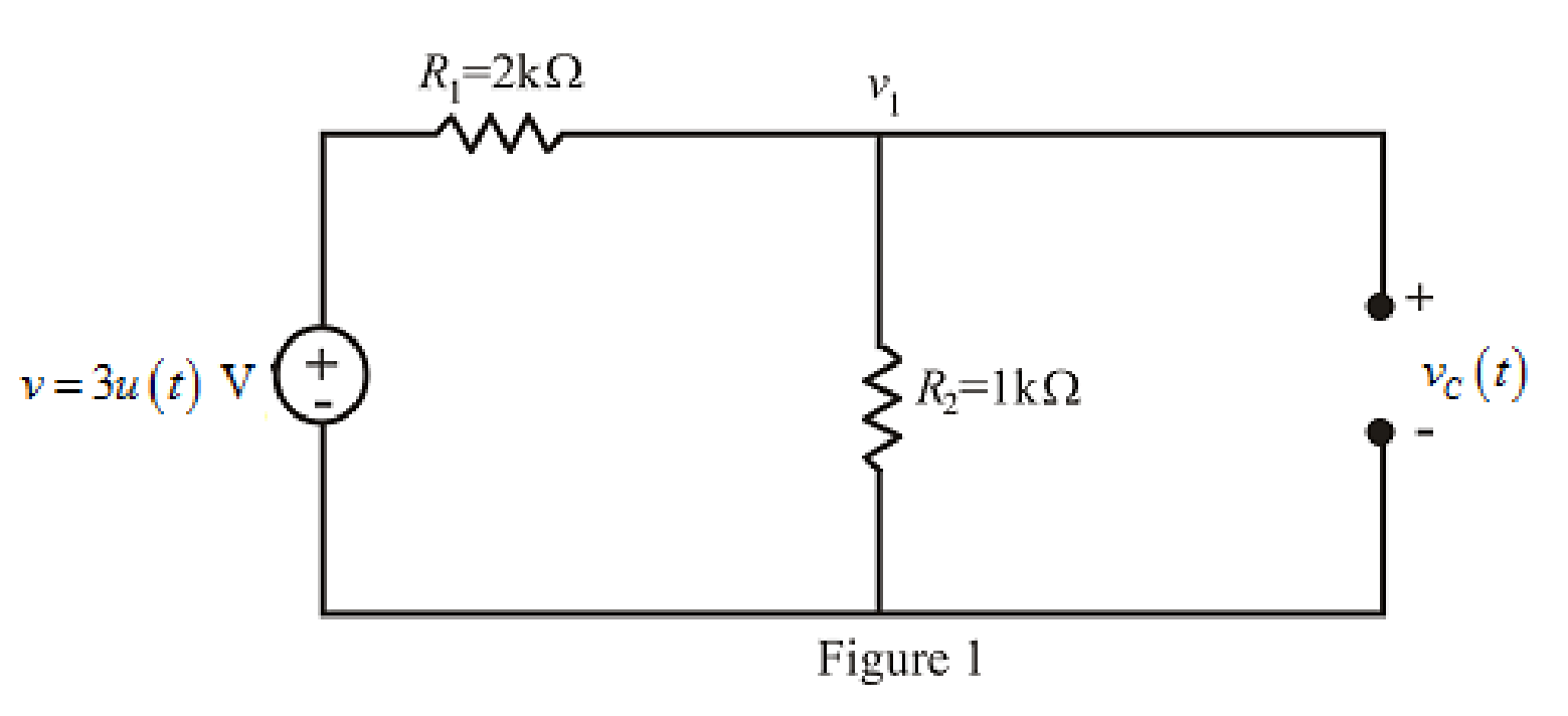
Refer to the redrawn Figure 1:
The given circuit is connected for long time,
So, capacitor behaves as open circuit.
The independent voltage source is unit step function.
The unit-step forcing function as a function of time which is zero for all values of its argument less than zero and which is unity for all positive values of its argument.
Here,
The independent voltage source is:
Substitute
Apply KCL at node 1.
Here,
Substitute
Rearrange for
So, at
The voltage across capacitorat
So,
Substitute
So, the value of the voltage across
Substitute
Rearrange for
So, the voltage
The redrawn circuit diagram is given in Figure 2.
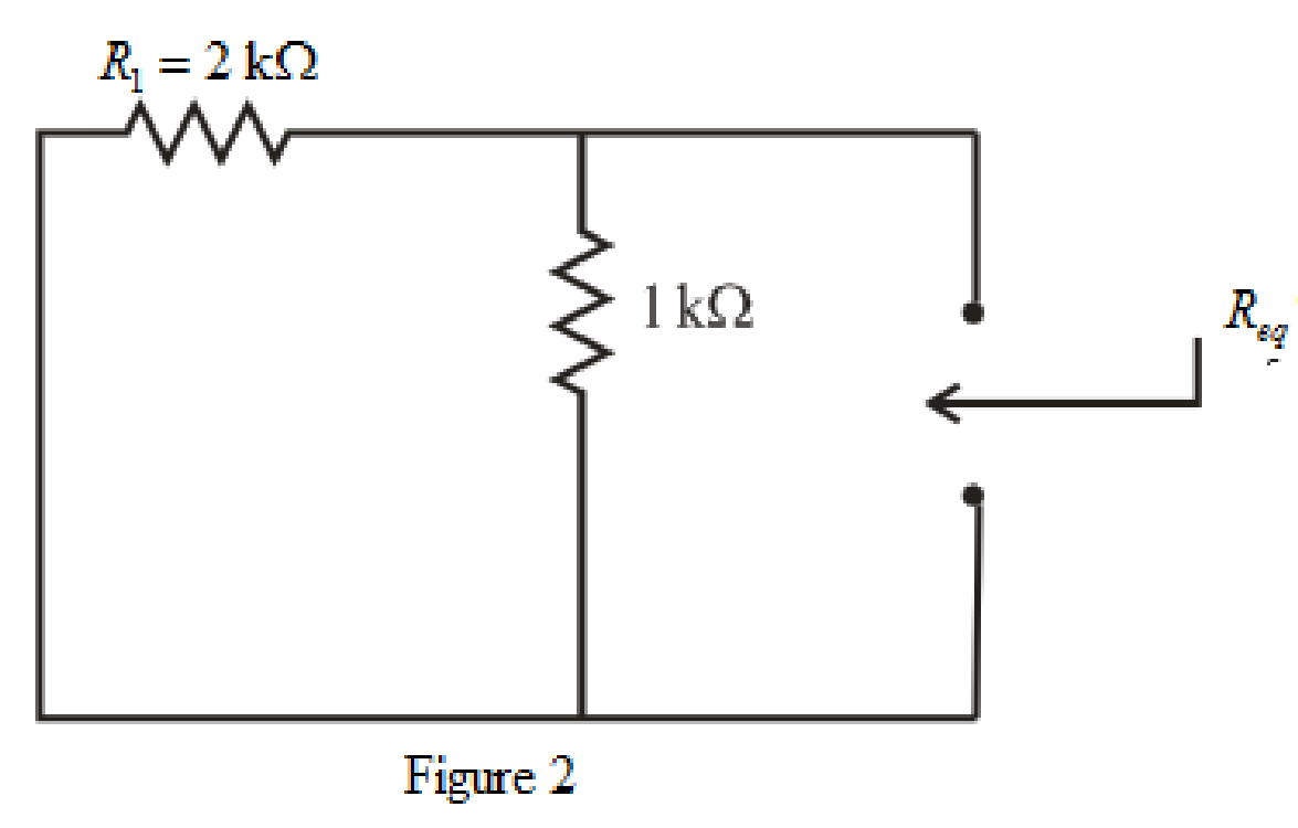
Refer to the redrawn Figure 2:
So, form equation (1),
Rearrange the equation for
The simplified diagram is shown in Figure 3.
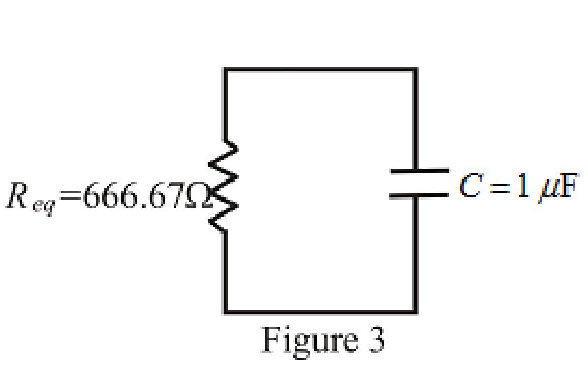
Refer to the redrawn Figure. 3:
Substitute
Substitute
So, the expression for the voltage across the capacitor valid for all values of
Conclusion:
Thus, the expression for
(b)
Sketch
(b)
Explanation of Solution
Given Data:
The range for the time is
Calculation:
Substitute
Substitute
Substitute
Substitute
Substitute
Substitute
Substitute
Substitute
Substitute
The different values of the
The graph for
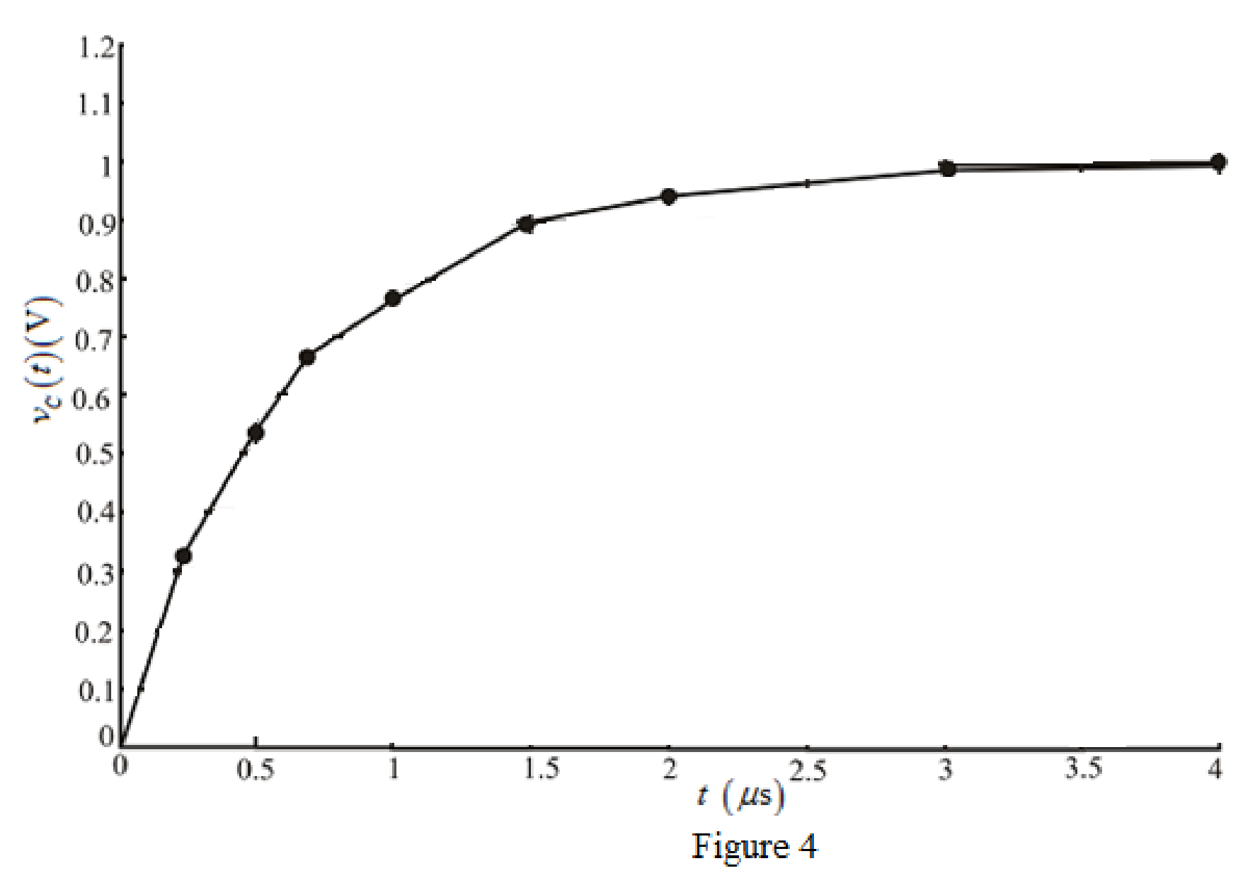
Conclusion:
Thus, the graph for
Want to see more full solutions like this?
Chapter 8 Solutions
ENGINEERING CIRCUIT...(LL)>CUSTOM PKG.<


- Find the valve of voltage V, and Va using LOOP analys is C ЗА Mw 8 ДАДА 2 Am 4 38 + V Z 4 5A 34 2 12Varrow_forward1. For the following logic gates: a. Write a Truth Table and logic equation? A Y A A. Y A Y "0" A A neotoof "0"> Day Y "1" A ADY DY A B DD A B b. What each of these gates represent? 2. Connect and draw the following digital logic equations: a. Y=X+1 b. Y=X+X' = \ c. Y=X X' d. Y=X 0 e. Y=XX' f. Y=XOX 3. Prove that: a. X(Y+Z)=XY+XZ b. X+YZ=(X+Y)(X+Z) c. (X+Y)'=X'Y' d. (XY)'=X'+Y e. X+XY=X f. X(X+Y)=Xarrow_forwardI need help with this problem and an step by step explanation of the solution from the image described below. (Introduction to Signals and Systems: Spectrum Representation)arrow_forward
- I need help with this problem and an step by step explanation of the solution from the image described below. (Introduction to Signals and Systems: A complex Numbers)arrow_forward5) Find the value of voltage V, and V₂ using Loop analysis. 5A + 4 34 ww 8 2 www 3A m 4 38 + 23V₂ 1/2 + ±) 12Varrow_forward4) Find the valve of voltage Vx using Loop analysis. 2A ( 1 3 w + 234 OV + 123arrow_forward
 Introductory Circuit Analysis (13th Edition)Electrical EngineeringISBN:9780133923605Author:Robert L. BoylestadPublisher:PEARSON
 Delmar's Standard Textbook Of ElectricityElectrical EngineeringISBN:9781337900348Author:Stephen L. HermanPublisher:Cengage Learning
 Programmable Logic ControllersElectrical EngineeringISBN:9780073373843Author:Frank D. PetruzellaPublisher:McGraw-Hill Education
 Fundamentals of Electric CircuitsElectrical EngineeringISBN:9780078028229Author:Charles K Alexander, Matthew SadikuPublisher:McGraw-Hill Education
 Electric Circuits. (11th Edition)Electrical EngineeringISBN:9780134746968Author:James W. Nilsson, Susan RiedelPublisher:PEARSON
 Engineering ElectromagneticsElectrical EngineeringISBN:9780078028151Author:Hayt, William H. (william Hart), Jr, BUCK, John A.Publisher:Mcgraw-hill Education,