Concept explainers
For the transistor configuration in Fig. 8.126:
a. Solve for the currents
b. Find the voltages
c. What is the ratio of output current
[Note: In transistor analysis, this ratio is referred to as the dc beta of the transistor (
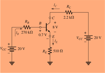
Fig. 8.126
Want to see the full answer?
Check out a sample textbook solutionChapter 8 Solutions
Introductory Circuit Analysis (13th Edition)
- (006) (2)- Problem - Common Emitter-Follower Amplifier. (Course: Electronic Devices and Circuit Theory). -Use Equation Operators or write it down on paper/digital paper. -Redraw and Apply. -You can add //comments for a better understanding. -Please answer without abbreviation. -Make it clean and clear typing/writing. Thank you.arrow_forward22. Three resistances Rab Rbc and Rca are connected in delta. Obtain expressions for their equivalent star resistances. AUTH D'arrow_forwardKindly answer the Bipolar Junction transistor Circuit letters a, b, and carrow_forward
- Subject : Power electronicsarrow_forward(7) Determine IB, IC, IE, VB,and Vc in the following figure, where BDC is 48. IF www Re 12KQ Rc 1.2KQ Vac 201 FIFarrow_forwardA) For the drauit of Figure 8, determine the following parameters: Ig, Ip, Vas, VD. VBc and then state the mode in which the BJT is operating. Useeither the gaphical (using a graph paper) approach or the mathematical approach Vcc Given: RC Vcc = 20 V R3 IDss = 8 mA %3D Vc p =-4 V Vss =-1V B =100 Vo RB = 470 2 %3! Rc = 36 k2 Rs =1 k2 RG RG = 2 MN Rs Vssarrow_forward
- The 36-cell PV module described in Example 8.4 had a parallel resistance per cell of Rp = 6.6 _ .In full sun and at current I = 2.14 A the output voltage was found there to be V = 19.41 V. If one cell is shaded and this current somehow stays the same, then: a. What would be the new module output voltage and power? b. What would be the voltage drop across the shaded cell? c. How much power would be dissipated in the shaded cell?arrow_forward3. The network of Figure below is the basic biasing arrangement for the field-effect transistor (FET), a device of increasing importance in electronic design. (Biasing simply means the application of de levels to establish a particular set of operating conditions.) Even though you may be unfamiliar with the FET, you can perform the following analysis using only the basic laws introduced in your lectures and the information provided on the diagram. a. Determine the voltages VG and Vs. b. Find the currents I1, 12, Ip, and Is. c. Determine VDs. d. Calculate VDG. VDD = 16 V ID 2 MN Rp 2.5 kn R1 오D VGO G = -1.75 V 2l V s O's Is Ic = 0 A Ip = Is R2 270 kn Rs 1.5 kNarrow_forward3. The network of Figure below is the basic biasing arrangement for the field-effect transistor (FET), a device of increasing importance in electronic design. (Biasing simply means the application of de levels to establish a particular set of operating conditions.) Even though you may be unfamiliar with the FET, you can perform the following analysis using only the basic laws introduced in your lectures and the information provided on the diagram. a. Determine the voltages VG and Vs. b. Find the currents I1, 2, ID, and Is. c. Determine VDs- d. Calculate VDG- VDD = 16 V 오 ID R1 2 MN RD 2.5 kN 오D VGO VGs = -1.75 V IG = 0A Ip = Is IG VGS Is oVs R2 270 kn Rs 1.5 kNarrow_forward
- 3. The network of Figure below is the basic biasing arrangement for the field-effect transistor (FET), a device of increasing importance in electronic design. (Biasing simply means the application of de levels to establish a particular set of operating conditions.) Even though you may be unfamiliar with the FET, you can perform the following analysis using only the basic laws introduced in your lectures and the information provided on the diagram. a. Determine the voltages VG and Vs. b. Find the currents I1, I2, ID, and Is. c. Determine VDS- d. Calculate DG- VDD = 16 V to ID 2 MN Rp32.5 kN R1 오D VGO VGs = -1.75 V IG = 0 A Ip = Is I IG VGS Is OVs R2 270 k2 Rs 1.5 kNarrow_forward3. The network of Figure below is the basic biasing arrangement for the field-effect transistor (FET), a device of increasing importance in electronic design. (Biasing simply means the application of de levels to establish a particular set of operating conditions.) Even though you may be unfamiliar with the FET, you can perform the following analysis using only the basic laws introduced in your lectures and the information provided on the diagram. a. Determine the voltages Vg and V's. b. Find the currents I1, I2, Ip, and Is. c. Determine Vos. d. Calculate VpG. Vpo = 16 V 오 R1 2 Mn Rp2.5 kn OD VGO Ves = -1.75 V IG - 0A In - Is VGS o's Is IS R2 270 kf Rs 1.5 knarrow_forward3. The network of Figure below is the basic biasing arrangement for the field-effect transistor (FET), a device of increasing importance in electronic design. (Biasing simply means the application of de levels to establish a particular set of operating conditions.) Even though you may be unfamiliar with the FET, you can perform the following analysis using only the basic laws introduced in your lectures and the information provided on the diagram. a. Determine the voltages VG and Vs. b. Find the currents I1, I2, ID, and Is. c. Determine V Ds- d. Calculate VpG- VDD = 16 V 오 ID R1 2 ΜΩ Rp 2.5 kN OD VGO IG VGs = -1.75 V 2 VGS IG = 0 A In = Is o's |Is R2 270 kN Rs 1.5 kNarrow_forward
- Introductory Circuit Analysis (13th Edition)Electrical EngineeringISBN:9780133923605Author:Robert L. BoylestadPublisher:PEARSONDelmar's Standard Textbook Of ElectricityElectrical EngineeringISBN:9781337900348Author:Stephen L. HermanPublisher:Cengage LearningProgrammable Logic ControllersElectrical EngineeringISBN:9780073373843Author:Frank D. PetruzellaPublisher:McGraw-Hill Education
- Fundamentals of Electric CircuitsElectrical EngineeringISBN:9780078028229Author:Charles K Alexander, Matthew SadikuPublisher:McGraw-Hill EducationElectric Circuits. (11th Edition)Electrical EngineeringISBN:9780134746968Author:James W. Nilsson, Susan RiedelPublisher:PEARSONEngineering ElectromagneticsElectrical EngineeringISBN:9780078028151Author:Hayt, William H. (william Hart), Jr, BUCK, John A.Publisher:Mcgraw-hill Education,