
Introductory Circuit Analysis (13th Edition)
13th Edition
ISBN: 9780133923605
Author: Robert L. Boylestad
Publisher: PEARSON
expand_more
expand_more
format_list_bulleted
Concept explainers
Videos
Textbook Question
Chapter 8, Problem 28P
- Redraw the network of Fig. 8.125 in a manner that will remove the crossover.
- Write the mesh equations for the network using the general approach.
- Calculate the mesh currents for the network.
- Find the total power delivered by the two sources
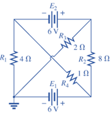
Fig. 8.125
Expert Solution & Answer
Want to see the full answer?
Check out a sample textbook solution
Students have asked these similar questions
Can you rewrite the solution because it is
unclear?
AM
(+) = 8(1+0.5 cos 1000kt +0.5 ros 2000 thts)
=
cos 10000 πt.
8 cos wat + 4 cos wit + 4 cos Wat coswet.
J4000 t
j11000rt
$14+) = 45
jqooort
+4e
+ e
+ e
j 12000rt.
12000 kt
+ e
+e
+e
Le
jsoort
-; goon t
te
+e
Dcw>
= 885(W- 100007) + 8 IS (W-10000) -
USB
Can you rewrite the solution because it is
unclear?
Q2
AM
①(+) = 8 (1+0.5 cos 1000πt +0.5 ros 2000kt)
$4+) = 45
=
*cos 10000 πt.
8 cos wat + 4 cosat + 4 cos Wat coswet.
j1000016
+4e
-j10000πt j11000Rt
j gooort -j 9000 πt
+
e
+e
j sooort
te
+e
J11000 t
+ e
te
j 12000rt.
-J12000 kt
+ с
= 8th S(W- 100007) + 8 IS (W-10000)
<&(w) =
USB
-5-5
-4-5-4
b) Pc 2² = 64
PSB =
42
+ 4
2
Pt Pc+ PSB =
y = Pe
c) Puss =
PLSB =
= 32
4² = 8 w
32+ 8 =
× 100% = 140
(1)³×2×2
31
= 20%
x 2 = 3w
302
USB
4.5 5 5.6 6
ms Ac = 4 mi
= 0.5
mz Ac = 4
५
M2
=
=0.5
A. Draw the waveform for the following binary sequence using Bipolar RZ, Bipolar NRZ, and
Manchester code.
Data sequence= (00110100)
B. In a binary PCM system, the output signal-to-quantization ratio is to be hold to a minimum of
50 dB. If the message is a single tone with fm-5 kHz. Determine:
1) The number of required levels, and the corresponding output signal-to-quantizing noise ratio.
2) Minimum required system bandwidth.
Chapter 8 Solutions
Introductory Circuit Analysis (13th Edition)
Ch. 8 - For the network of Fig. 8.103: a. Find the...Ch. 8 - For the network of Fig. 8.104: a. Determine the...Ch. 8 - Find voltage Vs (with polarity) across the ideal...Ch. 8 - For the network in Fig. 8.106: a. Find voltage Vs....Ch. 8 - Find the voltage V3 and the current I2 for the...Ch. 8 - For the network in Fig. 8.108: a. Find the...Ch. 8 - Convert the voltage sources in Fig. 8.109 to...Ch. 8 - Convert the current sources in Fig. 8.110 to...Ch. 8 - For the network in Fig. 8.111: Find the current IL...Ch. 8 - For the configuration of Fig. 8.112: a. Convert...
Ch. 8 - For the network in Fig. 8.113: a. Replace all the...Ch. 8 - Find the voltage Vs and the current I1 for the...Ch. 8 - Convert the voltage sources in Fig. 8.115 to...Ch. 8 - For the network in Fig. 8.116, reduce the network...Ch. 8 - Using branch-current analysis, find the magnitude...Ch. 8 - For the network of Fig. 8.118: Determine the...Ch. 8 - Using branch-current analysis, find the current...Ch. 8 - Using branch-current analysis, find the current...Ch. 8 - For the network in Fig. 8.121: a. Write the...Ch. 8 - Using the general approach to mesh analysis,...Ch. 8 - Using the general approach to mesh analysis,...Ch. 8 - Using the general approach to mesh analysis,...Ch. 8 - Using the general approach to mesh analysis,...Ch. 8 - Determine the mesh currents for the network of...Ch. 8 - Write the mesh equations for the network of Fig....Ch. 8 - Write the mesh equations for thesss network of...Ch. 8 - Write the mesh currents for the network of Fig....Ch. 8 - Redraw the network of Fig. 8.125 in a manner that...Ch. 8 - For the transistor configuration in Fig. 8.126: a....Ch. 8 - Using the supermesh approach, find the current...Ch. 8 - Using the supermesh approach, find the current...Ch. 8 - Using the format approach to mesh analysis, write...Ch. 8 - Using the format approach to mesh analysis, write...Ch. 8 - Using the format approach to mesh analysis, write...Ch. 8 - Write the mesh equations for the network of Fig....Ch. 8 - Write the mesh equations for the network of Fig....Ch. 8 - a. Write the mesh equations for the network of...Ch. 8 - Write the mesh equations for the network of Fig....Ch. 8 - Write the mesh equations for the network of Fig....Ch. 8 - a. Write the mesh equations for the network of...Ch. 8 - a. Write the nodal equations using the general...Ch. 8 - Write the nodal equations using the general...Ch. 8 - a. Write the nodal equations using the general...Ch. 8 - a. Write the nodal equations for the network of...Ch. 8 - a. Write the nodal equations for the network of...Ch. 8 - a. Write the nodal equations for the network of...Ch. 8 - Write the nodal equations for the network of Fig....Ch. 8 - Write the nodal equations for the network of Fig....Ch. 8 - Write the nodal equations for the network of Fig....Ch. 8 - Using the supernode approach, determine the nodal...Ch. 8 - Using the supernode approach, determine the nodel...Ch. 8 - Determine the nodal voltages of Fig. 8.130 using...Ch. 8 - Convert the voltage source of Fig 8.131 to a...Ch. 8 - Convert the voltage source of Fig. 8.136 to a...Ch. 8 - Apply the format approach of nodal analysis to the...Ch. 8 - Using the format approach, find the nodal voltages...Ch. 8 - Convert the voltage sources of Fig. 8.129 to...Ch. 8 - For the network of Fig. 8.135: a. Convert the...Ch. 8 - For the bridge network in Fig. 8.141: a. Write the...Ch. 8 - For the network in Fig. 8.141: a. Write the nodal...Ch. 8 - For the bridge in Fig. 8.142: a. Write the mesh...Ch. 8 - For the bridge network in Fig. 8.142: a. Write the...Ch. 8 - Determine the current through the source resistor...Ch. 8 - Repeat Problem 63 for the network of Fig. 8.144....Ch. 8 - Using a -Y or Y- conversion, find the current I...Ch. 8 - Convert the of 6.8 k resistors in Fig. 8.146 to...Ch. 8 - For the network of Fig. 8.147, find the current I...Ch. 8 - a. Using a -Y or Y- conversion, find the current...Ch. 8 - The network of Fig. 8.149 is very similar to the...Ch. 8 - a. Replace the TT configuration in Fig.8.150...Ch. 8 - Using Y or Yconversion, determine the total...Ch. 8 - Using schematics, find the current through each...Ch. 8 - Using schematics, find the mesh currents for the...Ch. 8 - Using schematics, determine the nodal voltages for...
Additional Engineering Textbook Solutions
Find more solutions based on key concepts
17–1C A high-speed aircraft is cruising in still air. How does the temperature of air at the nose of the aircra...
Thermodynamics: An Engineering Approach
A nozzle at A discharges water with an initial velocity of 36 ft/s at an angle with the horizontal. Determine ...
Vector Mechanics For Engineers
3.3 It is known that a vertical force of 200 lb is required to remove the nail at C from the board. As the nail...
Vector Mechanics for Engineers: Statics
CONCEPT QUESTIONS
15.CQ3 The ball rolls without slipping on the fixed surface as shown. What is the direction ...
Vector Mechanics for Engineers: Statics and Dynamics
How is the hydrodynamic entry length defined for flow in a pipe? Is the entry length longer in laminar or turbu...
Fluid Mechanics: Fundamentals and Applications
1.2 Explain the difference between geodetic and plane
surveys,
Elementary Surveying: An Introduction To Geomatics (15th Edition)
Knowledge Booster


Learn more about
Need a deep-dive on the concept behind this application? Look no further. Learn more about this topic, electrical-engineering and related others by exploring similar questions and additional content below.Similar questions
- Find Io using Mesh analysisarrow_forwardFM station of 100 MHz carrier frequency modulated by a 20 kHz sinusoid with an amplitude of 10 volt, so that the peak frequency deviation is 25 kHz determine: 1) The BW of the FM signal. 2) The approximated BW if the modulating signal amplitude is increased to 50 volt. 3) The approximated BW if the modulating signal frequency is increased by 70%. 4) The amplitude of the modulating signal if the BW is 65 kHz.arrow_forwardAn FDM is used to multiplex two groups of signals using AM-SSB, the first group contains 25 speech signals, each has maximum frequency of 4 kHz, the second group contains 15 music signals, each has maximum frequency of 10 kHz. A guard bandwidth of 500 Hz is used bety each two signals and before the first one. 1. Find the BWmultiplexing 2. Find the BWtransmission if the multiplexing signal is modulated using AM-DSB-LC.arrow_forward
- An FM signal with 75 kHz deviation, has an input signal-to-noise ratio of 18 dB, with a modulating frequency of 15 kHz. 1) Find SNRO at demodulator o/p. 2) Find SNRO at demodulator o/p if AM is used with m=0.3. 3) Compare the performance in case 1) and 2).. Hint: for single tone AM-DSB-LC, SNR₁ = (2m²) (4)arrow_forwardFind Va and Vb using Nodal analysisarrow_forwardCalculate the nodal voltage in the circuitarrow_forward
- Calculate the mesh currents, find Ia, Ib, Ic. Apply mesh analysisarrow_forwardFind Va and Vb using Nodal analysisarrow_forward4. A battery operated sensor transmits to a receiver that is plugged in to a power outlet. The device is continuously operated. The battery is a 3.6 V coin-cell battery with a 245mAHr capacity. The application requires a bit rate of 36 Mbps and an error rate of less than 10^-3. The channel has a center frequency of 2.4 GHz, a bandwidth of 10 MHz and a noise power spectral density of 10^-14 W/Hz. The maximum distance is 36 meters and the losses in the channel attenuates the signal by 0.25 dB/meter. Your company has two families of chips that you can use. An M-ary ASK and an M-ary QAM chip. The have very different power requirements as shown in the table below. The total current for the system is the current required to achieve the desired Eb/No PLUS the current identified below: Hokies PSK Chip Set Operating Current NOT Including the required Eb/No for the application Hokies QAM Chip Set Operating Current NOT Including the required Eb/No for the application Chip ID M-ary Voltage (volts)…arrow_forward
- Using the 802.11a specifications given below, in Matlab (or similar tool) create the time domain signal for one OFDM symbol using QPSK modulation. See attached plot for the QPSK constellation. Your results should include the power measure in the time and frequency domain and comment on those results. BW 802.11a OFDM PHY Parameters 20 MHZ OBW Subcarrer Spacing Information Rate Modulation Coding Rate Total Subcarriers Data Subcarriers Pilot Subcarriers DC Subcarrier 16.6 MHZ 312.5 Khz (20MHz/64 Pt FFT) 6/9/12/18/24/36/48/54 Mbits/s BPSK, QPSK, 16QAM, 64QAM 1/2, 2/3, 3/4 52 (Freq Index -26 to +26) 48 4 (-21, -7, +7, +21) *Always BPSK Null (0 subcarrier) 52 subarriers -7 (48 Data, 4 Pilot (BPSK), 1 Null) -26 -21 0 7 21 +26 14 One Subcarrier 1 OFDM symbol 1 OFDM Burst -OBW 16.6 MHz BW 20 MHZ 1 constellation point = 52 subcarriers = one or more OFDM symbols 802.11a OFDM Physical Parameters Show signal at this point x bits do Serial Data d₁ S₁ Serial-to- Input Signal Parallel Converter IFFT…arrow_forwardFind Vb and Va using Mesh analysisarrow_forward1. The communication channel bandwidth is 25 MHz centered at 1GHz and has a noise power spectral density of 10^-9 W/Hz. The channel loss between the transmitter and receiver is 25dB. The application requires a bit rate of 200Mbps and BER of less than 10^-4. Excluding Mary FSK, Determine the minimum transmit power required.arrow_forward
arrow_back_ios
SEE MORE QUESTIONS
arrow_forward_ios
Recommended textbooks for you
 Delmar's Standard Textbook Of ElectricityElectrical EngineeringISBN:9781337900348Author:Stephen L. HermanPublisher:Cengage Learning
Delmar's Standard Textbook Of Electricity
Electrical Engineering
ISBN:9781337900348
Author:Stephen L. Herman
Publisher:Cengage Learning
Kirchhoff's Rules of Electrical Circuits; Author: Flipping Physics;https://www.youtube.com/watch?v=d0O-KUKP4nM;License: Standard YouTube License, CC-BY