
Introductory Circuit Analysis (13th Edition)
13th Edition
ISBN: 9780133923605
Author: Robert L. Boylestad
Publisher: PEARSON
expand_more
expand_more
format_list_bulleted
Concept explainers
Videos
Textbook Question
Chapter 8, Problem 30P
Using the supermesh approach, find the current through each element of the network of Fig. 8.127.
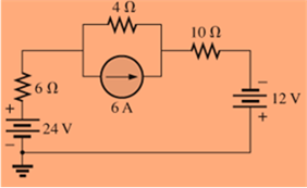
Fig. 8.127
Expert Solution & Answer
Want to see the full answer?
Check out a sample textbook solution
Students have asked these similar questions
=
Calculate Avf, Zif, and Zof for the amplifier circuit,Assume he = 50,
hie 1.1k2, and identical transistors?
150kQ
Vs
5002
HH
+25v
10k
+6
· 47ΚΩ
47k2
4.7k0}
33 ΚΩ
4.7ΚΩ
10k
w
4.7kQ
HH
Vo
For the four-pole filter in Fig. (2), determine the capacitance values required to produce a critical frequency
of 2680 Hz if all the resistors in the RC low-pass circuits are 1.8 K. Also select values for the feedback
resistors to get a Butterworth response.
Note: For a Butterworth response, the damping factor must be 1.848 for the first stage and 0.765 for the second
stage.
(2)
Re
Res
ww
"
=
11
For the circuit shown in Fig. 2.20, the transistors are identica' and have the following
parameters: hje=50, hie = 1.1K, hr =0, and hoe = 0. Calculate Auf, Rif and Rof.
Ans: 45.4; 112 KN; 129N.
HH
150k
47k
R
25 V
10k
47k
4.7k
5μF
33k
4.7k
50µF
50µF
4.7k
4.7k
R₁
Roj
R1000
Chapter 8 Solutions
Introductory Circuit Analysis (13th Edition)
Ch. 8 - For the network of Fig. 8.103: a. Find the...Ch. 8 - For the network of Fig. 8.104: a. Determine the...Ch. 8 - Find voltage Vs (with polarity) across the ideal...Ch. 8 - For the network in Fig. 8.106: a. Find voltage Vs....Ch. 8 - Find the voltage V3 and the current I2 for the...Ch. 8 - For the network in Fig. 8.108: a. Find the...Ch. 8 - Convert the voltage sources in Fig. 8.109 to...Ch. 8 - Convert the current sources in Fig. 8.110 to...Ch. 8 - For the network in Fig. 8.111: Find the current IL...Ch. 8 - For the configuration of Fig. 8.112: a. Convert...
Ch. 8 - For the network in Fig. 8.113: a. Replace all the...Ch. 8 - Find the voltage Vs and the current I1 for the...Ch. 8 - Convert the voltage sources in Fig. 8.115 to...Ch. 8 - For the network in Fig. 8.116, reduce the network...Ch. 8 - Using branch-current analysis, find the magnitude...Ch. 8 - For the network of Fig. 8.118: Determine the...Ch. 8 - Using branch-current analysis, find the current...Ch. 8 - Using branch-current analysis, find the current...Ch. 8 - For the network in Fig. 8.121: a. Write the...Ch. 8 - Using the general approach to mesh analysis,...Ch. 8 - Using the general approach to mesh analysis,...Ch. 8 - Using the general approach to mesh analysis,...Ch. 8 - Using the general approach to mesh analysis,...Ch. 8 - Determine the mesh currents for the network of...Ch. 8 - Write the mesh equations for the network of Fig....Ch. 8 - Write the mesh equations for thesss network of...Ch. 8 - Write the mesh currents for the network of Fig....Ch. 8 - Redraw the network of Fig. 8.125 in a manner that...Ch. 8 - For the transistor configuration in Fig. 8.126: a....Ch. 8 - Using the supermesh approach, find the current...Ch. 8 - Using the supermesh approach, find the current...Ch. 8 - Using the format approach to mesh analysis, write...Ch. 8 - Using the format approach to mesh analysis, write...Ch. 8 - Using the format approach to mesh analysis, write...Ch. 8 - Write the mesh equations for the network of Fig....Ch. 8 - Write the mesh equations for the network of Fig....Ch. 8 - a. Write the mesh equations for the network of...Ch. 8 - Write the mesh equations for the network of Fig....Ch. 8 - Write the mesh equations for the network of Fig....Ch. 8 - a. Write the mesh equations for the network of...Ch. 8 - a. Write the nodal equations using the general...Ch. 8 - Write the nodal equations using the general...Ch. 8 - a. Write the nodal equations using the general...Ch. 8 - a. Write the nodal equations for the network of...Ch. 8 - a. Write the nodal equations for the network of...Ch. 8 - a. Write the nodal equations for the network of...Ch. 8 - Write the nodal equations for the network of Fig....Ch. 8 - Write the nodal equations for the network of Fig....Ch. 8 - Write the nodal equations for the network of Fig....Ch. 8 - Using the supernode approach, determine the nodal...Ch. 8 - Using the supernode approach, determine the nodel...Ch. 8 - Determine the nodal voltages of Fig. 8.130 using...Ch. 8 - Convert the voltage source of Fig 8.131 to a...Ch. 8 - Convert the voltage source of Fig. 8.136 to a...Ch. 8 - Apply the format approach of nodal analysis to the...Ch. 8 - Using the format approach, find the nodal voltages...Ch. 8 - Convert the voltage sources of Fig. 8.129 to...Ch. 8 - For the network of Fig. 8.135: a. Convert the...Ch. 8 - For the bridge network in Fig. 8.141: a. Write the...Ch. 8 - For the network in Fig. 8.141: a. Write the nodal...Ch. 8 - For the bridge in Fig. 8.142: a. Write the mesh...Ch. 8 - For the bridge network in Fig. 8.142: a. Write the...Ch. 8 - Determine the current through the source resistor...Ch. 8 - Repeat Problem 63 for the network of Fig. 8.144....Ch. 8 - Using a -Y or Y- conversion, find the current I...Ch. 8 - Convert the of 6.8 k resistors in Fig. 8.146 to...Ch. 8 - For the network of Fig. 8.147, find the current I...Ch. 8 - a. Using a -Y or Y- conversion, find the current...Ch. 8 - The network of Fig. 8.149 is very similar to the...Ch. 8 - a. Replace the TT configuration in Fig.8.150...Ch. 8 - Using Y or Yconversion, determine the total...Ch. 8 - Using schematics, find the current through each...Ch. 8 - Using schematics, find the mesh currents for the...Ch. 8 - Using schematics, determine the nodal voltages for...
Additional Engineering Textbook Solutions
Find more solutions based on key concepts
17–1C A high-speed aircraft is cruising in still air. How does the temperature of air at the nose of the aircra...
Thermodynamics: An Engineering Approach
The solid steel shaft AC has a diameter of 25 mm and is supported by smooth bearings at D and E. It is coupled ...
Mechanics of Materials (10th Edition)
CONCEPT QUESTIONS
15.CQ3 The ball rolls without slipping on the fixed surface as shown. What is the direction ...
Vector Mechanics for Engineers: Statics and Dynamics
This optional Google account security feature sends you a message with a code that you must enter, in addition ...
SURVEY OF OPERATING SYSTEMS
Why is the study of database technology important?
Database Concepts (8th Edition)
Assume a telephone signal travels through a cable at two-thirds the speed of light. How long does it take the s...
Electric Circuits. (11th Edition)
Knowledge Booster


Learn more about
Need a deep-dive on the concept behind this application? Look no further. Learn more about this topic, electrical-engineering and related others by exploring similar questions and additional content below.Similar questions
- A triangular wave is applied to the input of Fig. (3). Determine what the output should be and sketch its waveform in relation to the input. 10μs. 0 5μs 15 μs 0.001 μF R₁ w 2.2karrow_forwardA three-phase, 480-V, 60-Hz, 6-pole, Y-connected induction motor has its speed controlled by slip power. The circuit parameters are given: Rs=0.06 ohms, Rr=0.05 ohms, Xs=0.2 ohms, Xr=0.3 ohms and Xm=6 ohms. The turn ratio of the rotor to stator winding is n=0.8. The no-load losses of the motor are equal to 150 W. The rotor and stator cupper losses are equal to 249.21 W. The slip power losses are estimated to 8000W. The load torque is 173.61 N.m. at 700 rpm. The efficiency is equal to: Select one: a. 71.5% b. None of these c. 81.5% d. 91.5% Question 2 Consider a 3-phase, 460-V, 100-hp, 0.88 power factor lagging, 4-pole, 1728 RPM, 60 Hz, Y-connected induction motor. The operating slip is equal to: Select one: a. 0.05 b. 0.01 c. 0.04 d. None of these Question 3 A 3 phase, 10 kW, 1750 rpm, Y- connected 460 V, 60 Hz, 4 poles, Y-connected induction motor has the following parameters: Rs = 0.5 Ohms, Rr = 0.3 Ohms, Xs = 0.9 Ohms, Xr = 0.9 Ohms, Xm = 25 Ohms. The no load…arrow_forwardelectric plants do for hand writingarrow_forward
- A lighting load of 600 kW and a motor load of 707 kW at 0.707 p.f lagging are supplied by two alternators running in parallel. One machine supplies 900 kW at 0.9 p.f lagging. Find the load sharing and p.f of second machine?arrow_forwardPlease draw out the circuitsarrow_forwardQ2 but when you get to part 3, can you please draw it outarrow_forward
- please solve manually. I need the drawing and the values too. Thank you!arrow_forwardTwo alternators, Y-connected 6.6 kV supply a load of 3000 kW at 0.8 p.f lagging. The synchronous mpedance of first alternator is (0.5+j10) Q/ph and second alternator is (0.4+j12) /ph. First alternator delivers 150 amp at 0.875 lag p.f. The two alterators are shared load equally. Determine the current, p.f., induced e.m.f, load angel, and maximum developed power of each alternator?arrow_forwardA domestic load of 2300 kW at 0.88 p.f lagging and a motors load of 3400 kW at 0.85 p.f lagging are supplied by two alternators operating in parallel. If one alternator is delivering a load of 3300 kW at 0.9 p.f lagging, what will be the output power and p.f of the other alternator?arrow_forward
- Determine the value of Rr that necessary for the circuit in Fig.(2) to operate as an oscillator and then determine the frequency of oscillation. 0.001 F 0.001 F 0.001 F R₁ • 10 ΚΩ R₁ 10 k R • 10 ΚΩarrow_forward(a) For the circuit shown in Figure Q3(a) (RFC and Cc are forbias) (i) (ii) Draw the AC small signal equivalent circuit of the oscillator. From this equivalent circuit derive an equation for fo and the gain condition for the oscillations to start. VDD www RG eee RFC H Cc 北 5 C₁ L 000 C₂ Voarrow_forwardPlease solve this question step by step handwritten solution and do not use chat gpt or any ai toolsfor part ii) you may need to use nodal analysisarrow_forward
arrow_back_ios
SEE MORE QUESTIONS
arrow_forward_ios
Recommended textbooks for you
 Introductory Circuit Analysis (13th Edition)Electrical EngineeringISBN:9780133923605Author:Robert L. BoylestadPublisher:PEARSON
 Delmar's Standard Textbook Of ElectricityElectrical EngineeringISBN:9781337900348Author:Stephen L. HermanPublisher:Cengage Learning
 Programmable Logic ControllersElectrical EngineeringISBN:9780073373843Author:Frank D. PetruzellaPublisher:McGraw-Hill Education
 Fundamentals of Electric CircuitsElectrical EngineeringISBN:9780078028229Author:Charles K Alexander, Matthew SadikuPublisher:McGraw-Hill Education
 Electric Circuits. (11th Edition)Electrical EngineeringISBN:9780134746968Author:James W. Nilsson, Susan RiedelPublisher:PEARSON
 Engineering ElectromagneticsElectrical EngineeringISBN:9780078028151Author:Hayt, William H. (william Hart), Jr, BUCK, John A.Publisher:Mcgraw-hill Education,
Introductory Circuit Analysis (13th Edition)
Electrical Engineering
ISBN:9780133923605
Author:Robert L. Boylestad
Publisher:PEARSON
Delmar's Standard Textbook Of Electricity
Electrical Engineering
ISBN:9781337900348
Author:Stephen L. Herman
Publisher:Cengage Learning
Programmable Logic Controllers
Electrical Engineering
ISBN:9780073373843
Author:Frank D. Petruzella
Publisher:McGraw-Hill Education
Fundamentals of Electric Circuits
Electrical Engineering
ISBN:9780078028229
Author:Charles K Alexander, Matthew Sadiku
Publisher:McGraw-Hill Education
Electric Circuits. (11th Edition)
Electrical Engineering
ISBN:9780134746968
Author:James W. Nilsson, Susan Riedel
Publisher:PEARSON
Engineering Electromagnetics
Electrical Engineering
ISBN:9780078028151
Author:Hayt, William H. (william Hart), Jr, BUCK, John A.
Publisher:Mcgraw-hill Education,
Kirchhoff's Rules of Electrical Circuits; Author: Flipping Physics;https://www.youtube.com/watch?v=d0O-KUKP4nM;License: Standard YouTube License, CC-BY